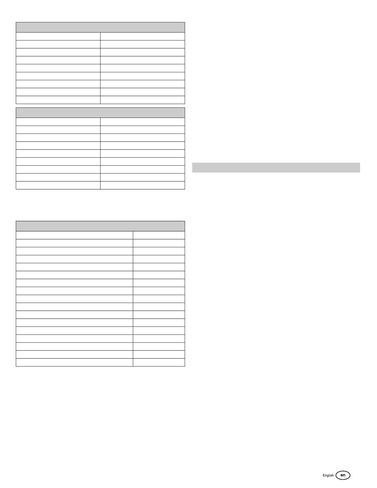
Simplicity 401577-0135-B2 Ohjekirja

Kategoria
Motor vehicle accessories & components
Tyyppi
Ohjekirja
Not for
Reproduction
80029973WST
Copyright © Briggs & Stratton Corporation
Milwaukee, WI, USA. All rights reserved.
Revision: A
Not for
Reproduction
1
2
3
4
5
6
7
8
9
10
2 BRIGGSandSTRATTON.com
Not for
Reproduction
11
12
13
14
15
3
Not for
Reproduction
Copyright © Briggs & Stratton Corporation, Milwaukee, WI, USA. All rights reserved.
This manual contains safety information to make you aware of the hazards and risks
associated with engines and how to avoid them. It also contains instructions for the proper
use and care of the engine. Because Briggs & Stratton Corporation does not necessarily
know what equipment this engine will power, it is important that you read and understand
these instructions and the instructions for the equipment. Save these original instructions
for future reference.
Note:
The figures and illustrations in this manual are provided for reference only and may
differ from your specific model. Contact your dealer if you have questions.
For replacement parts or technical assistance, record below the engine model, type, and
code numbers along with the date of purchase. These numbers are located on your engine
(see the
Features and Controls
section).
Date of Purchase
Engine Model - Type - Trim
Engine Serial Number
Look for the 2D barcode located on some
engines. When viewed with a 2D-capable
device, the code will bring up our website
where you can access support information
for this product. Data rates apply. Some
countries may not have online support
information available.
European Office Contact
Information
For questions regarding European emissions, please contact our European office at:
Max-Born-Straße 2, 68519 Viernheim, Germany.
Recycling Information
All packaging, used oil, and batteries should be recycled
according to applicable government regulations.
Operator Safety
Safety Alert Symbol and Signal Words
The safety alert symbol ( ) is used to identify safety information about hazards that can
result in personal injury. A signal word (DANGER, WARNING, or CAUTION) is used with
the alert symbol to indicate the likelihood and the potential severity of injury. In addition, a
hazard symbol may be used to represent the type of hazard.
DANGER indicates a hazard which, if not avoided, will result in death or serious
injury.
WARNING indicates a hazard which, if not avoided, could result in death or serious
injury.
CAUTION indicates a hazard which, if not avoided, could result in minor or moderate
injury.
NOTICE
indicates a situation that could result in damage to the product.
Hazard Symbols and Meanings
MeaningSymbolMeaningSymbol
Read and understand the
Operator's Manual before
operating or servicing the unit.
Safety information about
hazards that can result in
personal injury.
Explosion hazardFire hazard
Toxic fume hazardShock hazard
Noise hazard - Ear protection
recommended for extended
use.
Hot surface hazard
Explosion hazardThrown object hazard -
Wear eye protection.
Kickback hazardFrostbite hazard
Chemical HazardAmputation hazard - moving
parts
CorrosiveThermal heat hazard
Safety Messages
WARNING
This product can expose you to chemicals including gasoline engine exhaust, which is
known to the State of California to cause cancer, and carbon monoxide, which is known
to the State of California to cause birth defects or other reproductive harm. For more
information go to www.P65Warnings.ca.gov.
WARNING
Briggs & Stratton Engines are not designed for and are not to be used to power: fun-
karts; go-karts; children's, recreational, or sport all-terrain vehicles (ATVs); motorbikes;
hovercraft; aircraft products; or vehicles used in competitive events not sanctioned by
Briggs & Stratton. For information about competitive racing products, see
www.briggsracing.com. For use with utility and side-by-side ATVs, please contact Briggs
& Stratton Power Application Center, 1-866-927-3349. Improper engine application may
result in serious injury or death.
WARNING
Fuel and its vapors are extremely flammable and explosive.
Fire or explosion can cause severe burns or death.
When Adding Fuel
Turn engine off and let engine cool at least 2 minutes before removing the fuel cap.
Fill fuel tank outdoors or in well-ventilated area.
Do not overfill fuel tank. To allow for expansion of the fuel, do not fill above the bottom
of the fuel tank neck.
Keep fuel away from sparks, open flames, pilot lights, heat, and other ignition sources.
4 BRIGGSandSTRATTON.com
Not for
Reproduction
Check fuel lines, tank, cap, and fittings frequently for cracks or leaks. Replace if
necessary.
If fuel spills, wait until it evaporates before starting engine.
When Starting Engine
Ensure that spark plug, muffler, fuel cap and air cleaner (if equipped) are in place
and secured.
Do not crank engine with spark plug removed.
If engine floods, set choke (if equipped) to OPEN / RUN position, move throttle (if
equipped) to FAST position and crank until engine starts.
When Operating Equipment
Do not tip engine or equipment at angle which causes fuel to spill.
Do not choke the carburetor to stop engine.
Never start or run the engine with the air cleaner assembly (if equipped) or the air
filter (if equipped) removed.
When Changing Oil
If you drain the oil from the top oil fill tube, the fuel tank must be empty or fuel can
leak out and result in a fire or explosion.
When Tipping Unit for Maintenance
When performing maintenance that requires the unit to be tipped, the fuel tank, if
mounted on the engine, must be empty or fuel can leak out and result in a fire or
explosion.
When Transporting Equipment
Transport with fuel tank EMPTY or with fuel shut-off valve in the CLOSED position.
When Storing Fuel Or Equipment With Fuel In Tank
Store away from furnaces, stoves, water heaters or other appliances that have pilot
lights or other ignition sources because they can ignite fuel vapors.
WARNING
Starting engine creates sparking.
Sparking can ignite nearby flammable gases.
Explosion and fire could result.
If there is natural or LP gas leakage in area, do not start engine.
Do not use pressurized starting fluids because vapors are flammable.
WARNING
POISONOUS GAS HAZARD. Engine exhaust contains carbon monoxide, a
poisonous gas that could kill you in minutes. You CANNOT see it, smell it, or taste
it. Even if you do not smell exhaust fumes, you could still be exposed to carbon
monoxide gas. If you start to feel sick, dizzy, or weak while using this product,
get to fresh air RIGHT AWAY. See a doctor. You may have carbon monoxide
poisoning.
Operate this product ONLY outside far away from windows, doors and vents to reduce
the risk of carbon monoxide gas from accumulating and potentially being drawn
towards occupied spaces.
Install battery-operated carbon monoxide alarms or plug-in carbon monoxide alarms
with battery back-up according to the manufacturer's instructions. Smoke alarms
cannot detect carbon monoxide gas.
DO NOT run this product inside homes, garages, basements, crawlspaces, sheds,
or other partially-enclosed spaces even if using fans or opening doors and windows
for ventilation. Carbon monoxide can quickly build up in these spaces and can linger
for hours, even after this product has shut off.
ALWAYS place this product downwind and point the engine exhaust away from
occupied spaces.
WARNING
Rapid retraction of starter cord (kickback) will pull hand and arm toward engine
faster than you can let go.
Broken bones, fractures, bruises or sprains could result.
When starting engine, pull the starter cord slowly until resistance is felt and then pull
rapidly to avoid kickback.
Remove all external equipment / engine loads before starting engine.
Direct-coupled equipment components such as, but not limited to, blades, impellers,
pulleys, sprockets, etc., must be securely attached.
WARNING
Rotating parts can contact or entangle hands, feet, hair, clothing, or accessories.
Traumatic amputation or severe laceration can result.
Operate equipment with guards in place.
Keep hands and feet away from rotating parts.
Tie up long hair and remove jewelry.
Do not wear loose-fitting clothing, dangling drawstrings or items that could become
caught.
WARNING
Running engines produce heat. Engine parts, especially muffler, become extremely
hot.
Severe thermal burns can occur on contact.
Combustible debris, such as leaves, grass, brush, etc. can catch fire.
Allow muffler, engine cylinder and fins to cool before touching.
Remove accumulated debris from muffler area and cylinder area.
It is a violation of California Public Resource Code, Section 4442, to use or operate
the engine on any forest-covered, brush-covered, or grass-covered land unless the
exhaust system is equipped with a spark arrester, as defined in Section 4442,
maintained in effective working order. Other states or federal jurisdictions may have
similar laws. Contact the original equipment manufacturer, retailer, or dealer to obtain
a spark arrester designed for the exhaust system installed on this engine.
WARNING
Unintentional sparking can result in fire or electric shock.
Unintentional start-up can result in entanglement, traumatic amputation, or
laceration.
Fire hazard
Before performing adjustments or repairs:
Disconnect the spark plug wire and keep it away from the spark plug.
Disconnect battery at negative terminal (only engines with electric start.)
Use only correct tools.
Do not tamper with governor spring, links or other parts to increase engine speed.
Replacement parts must be of the same design and installed in the same position
as the original parts. Other parts may not perform as well, may damage the unit, and
may result in injury.
Do not strike the flywheel with a hammer or hard object because the flywheel may
later shatter during operation.
When testing for spark:
Use approved spark plug tester.
Do not check for spark with spark plug removed.
5
Not for
Reproduction
Features and Controls
Engine Controls
Compare the illustration (Figure: 1, 2) with your engine to familiarize yourself with the
location of various features and controls.
A. Engine Identification Numbers Model - Type - Code
B. Spark Plug
C. Air Cleaner
D. Dipstick
E. Oil Drain Plug
F. Air Intake Grille
G. Oil Filter
H. Electric Starter
I. Carburetor
J. Fuel Filter (if equipped)
K. Fuel Pump (if equipped)
L. Quick Oil Drain (if equipped)
M. Oil Cooler (if equipped)
N. Electric Control Unit (if equipped)
Engine Control Symbols and Meanings
MeaningSymbolMeaningSymbol
Engine speed - SLOWEngine speed - FAST
ON - OFFEngine speed - STOP
Engine start - Choke OPENEngine start - Choke
CLOSED
Fuel Shut-off - CLOSEDFuel Cap
Fuel Shut-off - OPEN
Fuel level - Maximum
Do not overfill
Operation
Oil Recommendations
Oil Capacity: See the
Specifications
section.
NOTICE
This engine was shipped from Briggs & Stratton without oil. Equipment manufacturers
or dealers may have added oil to the engine. Before you start the engine for the first
time, make sure to check the oil level and add oil according to the instructions in this
manual. If you start the engine without oil, it will be damaged beyond repair and will not
be covered under warranty.
We recommend the use of Briggs & Stratton Warranty Certified oils for best performance.
Other high-quality detergent oils are acceptable if classified for service SF, SG, SH, SJ or
higher. Do not use special additives.
Outdoor temperatures determine the proper oil viscosity for the engine. Use the chart to
select the best viscosity for the outdoor temperature range expected. Engines on most
outdoor power equipment operate well with 5W-30 Synthetic oil. For equipment operated
in hot temperatures, Vanguard™ 15W-50 Synthetic oil provides the best protection.
SAE 30 - Below 40 °F (4 °C) the use of SAE 30 will result in hard starting.A
10W-30 - Above 80 °F (27 °C) the use of 10W-30 may cause increased oil
consumption. Check oil level more frequently.
B
5W-30C
Synthetic 5W-30D
Vanguard™ Synthetic 15W-50E
Check Oil Level
See Figure: 3
Before adding or checking the oil
Make sure the engine is level.
Clean the oil fill area of any debris.
1. Remove the dipstick (A, Figure 3) and wipe with a clean cloth.
2. Install and tighten the dipstick (A, Figure 3).
3. Remove the dipstick and check the oil level. Correct oil level is at the top of the full
indicator (B, Figure 3 on the dipstick.
4. If oil level is low, slowly add oil into the engine oil fill (C, Figure 3). Do not overfill.
After adding oil, wait one minute and then recheck the oil level.
Note:
Do not add oil at the quick oil drain (D, Figure 3), if equipped.
5. Reinstall and tighten the dipstick (A, Figure 3).
Low Oil Protection System (if equipped)
Some engines are equipped with a low oil sensor. If the oil is low, the sensor will either
activate a warning light or stop the engine. Stop the engine and follow these steps before
restarting the engine.
Make sure the engine is level.
Check the oil level. See the
Check Oil Level
section.
If the oil level is low, add the proper amount of oil. Start the engine and make sure
the warning light (if equipped) is not activated.
If the oil level is not low, do not start the engine. Contact a Briggs & Stratton
Authorized Service Dealer to have the oil problem corrected.
Fuel Recommendations
Fuel must meet these requirements:
Clean, fresh, unleaded gasoline.
A minimum of 87 octane/87 AKI (91 RON). High altitude use, see below.
Gasoline with up to 10% ethanol (gasohol) is acceptable.
NOTICE
Do not use unapproved gasolines, such as E15 and E85. Do not mix oil in
gasoline or modify the engine to run on alternate fuels. Use of unapproved fuels will
damage the engine components, which will not be covered under warranty.
To protect the fuel system from gum formation, mix a fuel stabilizer into the fuel. See
Storage.
All fuel is not the same. If starting or performance problems occur, change fuel
6 BRIGGSandSTRATTON.com
Not for
Reproduction
providers or change brands. This engine is certified to operate on gasoline. The emissions
control system for this engine is EM (Engine Modifications).
High Altitude
At altitudes over 5,000 feet (1524 meters), a minimum 85 octane/85 AKI (89 RON) gasoline
is acceptable.
For carbureted engines, high altitude adjustment is required to maintain performance.
Operation without this adjustment will cause decreased performance, increased fuel
consumption, and increased emissions. Contact a Briggs & Stratton Authorized Service
Dealer for high altitude adjustment information. Operation of the engine at altitudes below
2,500 feet (762 meters) with the high altitude adjustment is not recommended.
For Electronic Fuel Injection (EFI) engines, no high altitude adjustment is necessary.
Add Fuel
See Figure: 4
WARNING
Fuel and its vapors are extremely flammable and explosive.
Fire or explosion can cause severe burns or death.
When adding fuel
Turn engine off and let engine cool at least 2 minutes before removing the fuel cap.
Fill fuel tank outdoors or in well-ventilated area.
Do not overfill fuel tank. To allow for expansion of the fuel, do not fill above the bottom
of the fuel tank neck.
Keep fuel away from sparks, open flames, pilot lights, heat, and other ignition sources.
Check fuel lines, tank, cap, and fittings frequently for cracks or leaks. Replace if
necessary.
If fuel spills, wait until it evaporates before starting engine.
1. Clean the fuel cap area of dirt and debris. Remove the fuel cap.
2. Fill the fuel tank (A, Figure 4) with fuel. To allow for expansion of the fuel, do not fill
above the bottom of the fuel tank neck (B).
3. Reinstall the fuel cap.
Start and Stop Engine
See Figure: 5
Start Engine
WARNING
Fuel and its vapors are extremely flammable and explosive.
Fire or explosion can cause severe burns or death.
When Starting Engine
Ensure that spark plug, muffler, fuel cap and air cleaner (if equipped) are in place
and secured.
Do not crank engine with spark plug removed.
If engine floods, set choke (if equipped) to OPEN / RUN position, move throttle (if
equipped) to FAST position and crank until engine starts.
WARNING
POISONOUS GAS HAZARD. Engine exhaust contains carbon monoxide, a
poisonous gas that could kill you in minutes. You CANNOT see it, smell it, or taste
it. Even if you do not smell exhaust fumes, you could still be exposed to carbon
monoxide gas. If you start to feel sick, dizzy, or weak while using this product,
shut it off and get to fresh air RIGHT AWAY. See a doctor. You may have carbon
monoxide poisoning.
Operate this product ONLY outside far away from windows, doors and vents to reduce
the risk of carbon monoxide gas from accumulating and potentially being drawn
towards occupied spaces.
Install battery-operated carbon monoxide alarms or plug-in carbon monoxide alarms
with battery back-up according to the manufacturer's instructions. Smoke alarms
cannot detect carbon monoxide gas.
DO NOT run this product inside homes, garages, basements, crawlspaces, sheds,
or other partially-enclosed spaces even if using fans or opening doors and windows
for ventilation. Carbon monoxide can quickly build up in these spaces and can linger
for hours, even after this product has shut off.
ALWAYS place this product downwind and point the engine exhaust away from
occupied spaces.
NOTICE
This engine was shipped from Briggs & Stratton without oil. Before you start
the engine, make sure you add oil according to the instructions in this manual. If you
start the engine without oil, it will be damaged beyond repair and will not be covered
under warranty.
Determine The Starting System
Before starting the engine, you must determine the type of starting system that is on your
engine. Your engine will have one of the following types.
ReadyStart
®
System: This features a temperature controlled automatic choke. It
does not have a primer.
Electronic Fuel Management System: This features an Electronic Control Unit that
monitors engine and temperature conditions. It does not have a manual choke or a
primer.
Choke System: This features a choke to be used for starting in cool temperatures.
Some models will have a separate choke control while others will have a combination
choke / throttle control. This type does not have a primer.
To start your engine, follow the instructions for your type of starting system.
Note:
Equipment may have remote controls. See the equipment manual for location and
operation of remote controls.
ReadyStart
®
System
1. Check the engine oil. See the
Check Oil Level
section.
2. Make sure equipment drive controls, if equipped, are disengaged.
3. Move the fuel shut-off (A, Figure 5), if equipped, to the OPEN position.
4. Move the throttle control (B, Figure 5), if equipped, to the FAST position. Operate
the engine in the FAST position.
Note:
For starting in cold weather temperatures (below 32° F), move the combination choke
and throttle lever (B C, Figure 5) to the CLOSED position.
5. Turn the electric start switch (D, Figure 5) to the ON or START position or push
button (E).
NOTICE
To extend the life of the starter, use short starting cycles (five seconds
maximum). Wait one minute between starting cycles.
Note:
If the engine does not start after repeated attempts, contact you local dealer or go
to BRIGGSandSTRATTON.com or call 1-800-233-3723 (in USA).
Electronic Fuel Management System
1. Check the engine oil. See the
Check Oil Level
section.
2. Make sure equipment drive controls, if equipped, are disengaged.
3. Move the fuel shut-off (A, Figure 5), if equipped, to the OPEN position.
4. Move the throttle control (B, Figure 5), if equipped, to the FAST position. Operate
the engine in the FAST position.
5. Turn the electric start switch (D, Figure 5) to the ON or START position.
NOTICE
To extend the life of the starter, use short starting cycles (five seconds
maximum). Wait one minute between starting cycles.
Note:
If the engine does not start after repeated attempts, contact you local dealer or go
to BRIGGSandSTRATTON.com or call 1-800-233-3723 (in USA).
Choke System
1. Check the engine oil. See the
Check Oil Level
section.
2. Make sure equipment drive controls, if equipped, are disengaged.
3. Move the fuel shut-off (A, Figure 5), if equipped, to the OPEN position.
4. Move the throttle control (B, Figure 5), if equipped, to the FAST position. Operate
the engine in the FAST position.
5. Move the choke control (C, Figure 5), or the combination throttle and choke lever (B
C, Figure 5), to the CLOSED position.
7
Not for
Reproduction
Note:
Choke is usually unnecessary when restarting a warm engine.
6. Turn the electric start switch (D, Figure 5) to the ON or START position.
NOTICE
To extend the life of the starter, use short starting cycles (five seconds
maximum). Wait one minute between starting cycles.
7. As the engine warms up, move the choke control (C, Figure 5) to the OPEN position.
Note:
If the engine does not start after repeated attempts, contact you local dealer or go
to BRIGGSandSTRATTON.com or call 1-800-233-3723 (in USA).
Stop Engine
WARNING
Fuel and its vapors are extremely flammable and explosive.
Fire or explosion can cause severe burns or death.
Do not choke the carburetor to stop the engine.
1. Move the throttle control (B, Figure 5) to the SLOW position.
2. Turn the key switch (D, Figure 5) to the OFF position. Remove the key and keep in
a safe place out of the reach of children.
3. After the engine stops, move the fuel shut-off (A, Figure 5), if equipped, to the
CLOSED position.
Maintenance
NOTICE
If the engine is tipped during maintenance, the fuel tank, if mounted on
engine, must be empty and the spark plug side must be up. If the fuel tank is not empty
and if the engine is tipped in any other direction, it may be difficult to start due to oil or
gasoline contaminating the air filter and/or the spark plug.
WARNING
When performing maintenance that requires the unit to be tipped, the fuel tank, if mounted
on the engine, must be empty or fuel can leak out and result in a fire or explosion.
We recommend that you see any Briggs & Stratton Authorized Service Dealer for all
maintenance and service of the engine and engine parts.
NOTICE
All the components used to build this engine must remain in place for proper
operation.
WARNING
Unintentional sparking can result in fire or electric shock.
Unintentional start-up can result in entanglement, traumatic amputation, or
laceration.
Fire hazard
Before performing adjustments or repairs:
Disconnect the spark plug wire and keep it away from the spark plug.
Disconnect battery at negative terminal (only engines with electric start.)
Use only correct tools.
Do not tamper with governor spring, links or other parts to increase engine speed.
Replacement parts must be of the same design and installed in the same position
as the original parts. Other parts may not perform as well, may damage the unit, and
may result in injury.
Do not strike the flywheel with a hammer or hard object because the flywheel may
later shatter during operation.
When testing for spark:
Use approved spark plug tester.
Do not check for spark with spark plug removed.
Emissions Control Service
Maintenance, replacement, or repair of the emissions control devices and systems
may be performed by any off-road engine repair establishment or individual. However,
to obtain "no charge" emissions control service, the work must be performed by a factory
authorized dealer. See the Emissions Control Statements.
Maintenance Schedule
First 5 Hours
Change oil
2
Every 8 Hours or Daily
Check engine oil level
Clean area around muffler and controls
Clean air intake grille
Every 25 Hours or Annually
Clean air filter
1
Clean pre-cleaner
1
Every 50 Hours or Annually
Change engine oil
3
Replace oil filter (if equipped)
3
Service exhaust system
Every 100 Hours or Annually
Change engine oil
4
Replace oil filter (if equipped)
4
Annually
Replace spark plug
Replace air filter
Replace pre-cleaner
Replace fuel filter
Service cooling system
1
Check valve clearance
5
1
In dusty conditions or when airborne debris is present, clean more often.
2
Only engines without oil filter.
3
Engine without oil filter or with standard black oil filter (see
Specifications
page
for part number).
4
Engines with high-efficiency yellow or orange oil filter (see
Specifications
page
for part number).
5
Not required unless engine performance problems are noted.
Electronic Fuel Management System
The Electronic Fuel Management System monitors engine temperature, engine speed,
and battery voltage to adjust the choke during engine starting and warm up. There are no
adjustments on the system. If starting or operation problems occur, contact an Authorized
Briggs & Stratton Dealer.
NOTICE
Make sure to follow the steps below or the Electronic Fuel Management
System could be damaged.
Never start the engine if the battery cables are loose.
Turn the key to the off position before disconnecting, removing and / or installing the
battery.
Never use a battery charger to start the engine.
Never disconnect the battery cables while the engine is running.
When connecting the battery cables, first connect the positive (+) cable and then
connect the negative (-) cable to the battery.
When charging the battery, turn the ignition switch to the off position and disconnect
the negative (-) battery cable from the battery.
Do not spray water directly on the Electronic Control Unit.
8 BRIGGSandSTRATTON.com
Not for
Reproduction
Carburetor and Engine Speed
Never make adjustments to the carburetor or engine speed. The carburetor was set at the
factory to operate efficiently under most conditions. Do not tamper with the governor spring,
linkages, or other parts to change the engine speed. If any adjustments are required contact
a Briggs & Stratton Authorized Service Dealer for service.
NOTICE
The equipment manufacturer specifies the maximum speed for the engine
as installed on the equipment. Do not exceed this speed. If you are unsure what the
equipment maximum speed is, or what the engine speed is set to from the factory,
contact a Briggs & Stratton Authorized Service Dealer for assistance. For safe and
proper operation of the equipment, the engine speed should be adjusted only by a
qualified service technician.
Service Spark Plug
See Figure: 6
Check the gap (A, Figure 6) with a wire gauge (B). If necessary, reset the gap. Install and
tighten the spark plug to the recommended torque. For gap setting or torque, see the
Specifications
section.
Note:
In some areas, local law requires using a resistor spark plug to suppress ignition
signals. If this engine was originally equipped with a resistor spark plug, use the same type
for replacement.
Service Exhaust System
WARNING
Running engines produce heat. Engine parts, especially muffler, become extremely
hot.
Severe thermal burns can occur on contact.
Combustible debris, such as leaves, grass, brush, etc. can catch fire.
Allow muffler, engine cylinder and fins to cool before touching.
Remove accumulated debris from muffler area and cylinder area.
It is a violation of California Public Resource Code, Section 4442, to use or operate
the engine on any forest-covered, brush-covered, or grass-covered land unless the
exhaust system is equipped with a spark arrester, as defined in Section 4442,
maintained in effective working order. Other states or federal jurisdictions may have
similar laws. Contact the original equipment manufacturer, retailer, or dealer to obtain
a spark arrester designed for the exhaust system installed on this engine.
Exhaust system parts are installed by the equipment manufacturer. For specific maintenance
and replacement parts information, contact the equipment manufacturer.
Remove accumulated debris from muffler and cylinder area. Inspect the muffler for cracks,
corrosion, or other damage. Remove the deflector or the spark arrester, if equipped, and
inspect for damage or carbon blockage. If damage is found, install replacement parts before
operating.
WARNING
Replacement parts must be of the same design and installed in the same position as
the original parts. Other parts may not perform as well, may damage the unit, and may
result in injury.
Change Engine Oil
See Figure: 7, 8, 9, 10
Used oil is a hazardous waste product and must be disposed of properly. Do not discard
with household waste. Check with your local authorities, service center, or dealer for safe
disposal/recycling facilities.
Remove Oil
1. With engine off but still warm, disconnect the spark plug wire (D, Figure 7) and keep
it away from the spark plug (E).
2. Remove the dipstick (A, Figure 8).
Oil Drain Plug, if equipped
1. Remove the oil drain plug (F, Figure 8). Drain the oil into an approved container.
Note:
Various oil drain plugs (G, Figure 8) are installed.
2. After the oil has drained, install and tighten the oil drain plug (F, Figure 8).
Quick Oil Drain, if equipped
1. Disconnect the quick oil drain hose (H, Figure 9) from the side of the engine.
2. Turn and remove the oil drain cap (I, Figure 9). Carefully lower the quick oil drain (H)
into an approved container (J).
3. After the oil has drained, install the quick oil drain cap (I, Figure 9). Attach the quick
oil drain hose (H) to the side of the engine.
Change Oil Filter, if equipped
Some models are equipped with an oil filter. For replacement intervals, see the
Maintenance Schedule.
1. Drain the oil from the engine. See
Remove Oil
section.
2. Remove the oil filter (K, Figure 10) and dispose of properly.
3. Before you install the new oil filter, lightly lubricate the oil filter gasket with fresh,
clean oil.
4. Install the oil filter by hand until the gasket contacts the oil filter adapter, then tighten
the oil filter 1/2 to 3/4 turns.
5. Add oil. See
Add Oil
section.
6. Start and run the engine. As the engine warms up, check for oil leaks.
7. Stop the engine and check the oil level. Correct oil level is at the top of the full indicator
(B, Figure 8) on the dipstick.
Add Oil
Make sure the engine is level.
Clean the oil fill area of any debris.
See the
Specifications
section for oil capacity.
1. Remove the dipstick (A, Figure 8) and wipe with a clean cloth.
2. Slowly pour oil into the engine oil fill (C, Figure 8). Do not overfill. After adding oil,
wait one minute and then check the oil level.
Note:
Do not add oil at the quick oil drain (H, Figure 9), if equipped.
3. Install and tighten the dipstick (A, Figure 8).
4. Remove the dipstick and check the oil level. Correct oil level is at the top of the full
indicator (B, Figure 8) on the dipstick.
5. Reinstall and tighten the dipstick (A, Figure 8).
6. Connect the spark plug wire (D, Figure 7) to the spark plug (E).
Service Air Filter
See Figure: 11, 12, 13
WARNING
Fuel and its vapors are extremely flammable and explosive.
Fire or explosion can cause severe burns or death.
Never start and run the engine with the air cleaner assembly (if equipped) or the air
filter (if equipped) removed.
NOTICE
Do not use pressurized air or solvents to clean the filter. Pressurized air can
damage the filter and solvents will dissolve the filter.
See the
Maintenance Schedule
for service requirements.
Various models use either a foam or a paper filter. Some models may also have an optional
pre-cleaner that can be washed and reused. Compare the illustrations in this manual with
the type installed on your engine and service as follows.
Paper Air Filter
1. Loosen the fastener(s) (A, Figure 11).
9
Not for
Reproduction
2. Remove the air filter cover (B, Figure 11).
3. Remove the filter (C, Figure 11) and the pre-cleaner (D), if equipped.
4. To loosen debris, gently tap the filter on a hard surface. If the filter is excessively
dirty, replace with a new filter.
5. Wash the pre-cleaner (D, Figure 11), if equipped, in liquid detergent and water. Allow
the pre-cleaner to thoroughly air dry. Do not oil the pre-cleaner.
6. Assemble the dry pre-cleaner (D, Figure 11), if equipped, and the filter (C) into the
air filter base (E).
7. Install the air filter cover (B, Figure 11) and secure with fastener(s) (A). Make sure
the fastener(s) is tight.
Paper Air Filter
1. Loosen the fastener(s) (A, Figure 12, 13).
2. Remove the air filter cover (B, Figure 12, 13).
3. To remove the filter (C, Figure 12, 13), lift the end of the filter.
4. To loosen debris, gently tap the filter on a hard surface. If the filter is excessively
dirty, replace with a new filter.
5. Remove the pre-cleaner (D, Figure 12, 13), if equipped, from the filter (C).
6. Wash the pre-cleaner (D, Figure 12, 13), if equipped, in liquid detergent and water.
Allow the pre-cleaner to thoroughly air dry. Do not oil the pre-cleaner.
7. Assemble the dry pre-cleaner (D, Figure 12, 13), if equipped, to the filter (C).
8. Install the filter (C, Figure 12, 13) and pre-cleaner (D), if equipped, into the filter base
(E) and push down until the filter snaps in place.
9. Install the air filter cover (B, Figure 12, 13) and secure with fastener(s) (A). Make
sure the fastener(s) is tight.
Service Fuel System
See Figure: 14
WARNING
Fuel and its vapors are extremely flammable and explosive.
Fire or explosion can cause severe burns or death.
Keep fuel away from sparks, open flames, pilot lights, heat, and other ignition sources.
Check fuel lines, tank, cap, and fittings frequently for cracks or leaks. Replace if
necessary.
Before cleaning or replacing the fuel filter, drain the fuel tank or close the fuel shut-
off valve.
If fuel spills, wait until it evaporates before starting engine.
Replacement parts must be the same and installed in the same position as the original
parts.
Fuel Filter, if equipped
1. Before replacing the fuel filter (A, Figure 14), if equipped, drain the fuel tank or close
the fuel shut-off valve. Otherwise, fuel can leak out and cause a fire or explosion.
2. Use pliers to squeeze tabs (B, Figure 14) on the clamps (C), then slide the clamps
away from the fuel filter (A). Twist and pull the fuel lines (D) off of the fuel filter.
3. Check the fuel lines (D, Figure 14) for cracks or leaks. Replace if necessary.
4. Replace the fuel filter (A, Figure 14) with an original equipment replacement filter.
5. Secure the fuel lines (D, Figure 14) with clamps (C) as shown.
Service Cooling System
WARNING
Running engines produce heat. Engine parts, especially muffler, become extremely
hot.
Severe thermal burns can occur on contact.
Combustible debris, such as leaves, grass, brush, etc., can catch fire.
Allow muffler, engine cylinder and fins to cool before touching.
Remove accumulated debris from muffler area and cylinder area.
NOTICE
Do not use water to clean the engine. Water could contaminate the fuel
system. Use a brush or dry cloth to clean the engine.
This is an air cooled engine. Dirt or debris can restrict air flow and cause the engine to
overheat, resulting in poor performance and reduced engine life.
1. Use a brush or dry cloth to remove debris from the air intake grille.
2. Keep linkage, springs and controls clean.
3. Keep the area around and behind the muffler, if equipped, free of any combustible
debris.
4. Make sure the oil cooler fins, if equipped, are free of dirt and debris.
After a period of time, debris can accumulate in the cylinder cooling fins and cause the
engine to overheat. This debris cannot be removed without partial disassembly of the
engine. Have a Briggs & Stratton Authorized Service Dealer inspect and clean the air
cooling system as recommended in the
Maintenance Schedule.
Storage
WARNING
Fuel and its vapors are extremely flammable and explosive.
Fire or explosion can cause severe burns or death.
When Storing Fuel Or Equipment With Fuel In Tank
Store away from furnaces, stoves, water heaters or other appliances that have pilot
lights or other ignition sources because they can ignite fuel vapors.
Fuel System
See Figure: 15
Store the engine level (normal operating position). Fill fuel tank (A, Figure 15) with fuel.
To allow for expansion of fuel, do not overfill above the fuel tank neck (B).
Fuel can become stale when stored over 30 days. Stale fuel causes acid and gum deposits
to form in the fuel system or on essential carburetor parts. To keep fuel fresh, use Briggs
& Stratton Advanced Formula Fuel Treatment & Stabilizer, available wherever Briggs
& Stratton genuine service parts are sold.
There is no need to drain gasoline from the engine if a fuel stabilizer is added according
to instructions. Run the engine for two (2) minutes to circulate the stabilizer throughout the
fuel system before storage.
If gasoline in the engine has not been treated with a fuel stabilizer, it must be drained into
an approved container. Run the engine until it stops from lack of fuel. The use of a fuel
stabilizer in the storage container is recommended to maintain freshness.
Engine Oil
While the engine is still warm, change the engine oil. See the
Change Engine Oil
section.
Troubleshooting
For assistance, contact your local dealer or go to BRIGGSandSTRATTON.com or call
1-800-233-3723 (in USA).
Specifications
Model: 400000
40.03 ci (656 cc)Displacement
2.970 in (75,43 mm)Bore
2.890 in (73,41 mm)Stroke
62 - 64 oz (1,8 - 1,9 L)Oil Capacity
.030 in (,76 mm)Spark Plug Gap
180 lb-in (20 Nm)Spark Plug Torque
.008 - .012 in (,20 - ,30 mm)Armature Air Gap
.004 - .006 in (,10 - ,15 mm)Intake Valve Clearance
.004 - .006 in (,10 - ,15 mm)Exhaust Valve Clearance
10 BRIGGSandSTRATTON.com
Not for
Reproduction
Model: 440000
44.18 ci (724 cc)Displacement
3.120 in (79,24 mm)Bore
2.890 in (73,41 mm)Stroke
62 - 64 oz (1,8 - 1,9 L)Oil Capacity
.030 in (,76 mm)Spark Plug Gap
180 lb-in (20 Nm)Spark Plug Torque
.008 - .012 in (,20 - ,30 mm)Armature Air Gap
.004 - .006 in (,10 - ,15 mm)Intake Valve Clearance
.004 - .006 in (,10 - ,15 mm)Exhaust Valve Clearance
Model: 490000
49.42 ci (810 cc)Displacement
3.300 in (83,81 mm)Bore
2.890 in (73,41 mm)Stroke
66 - 68 oz (1,9 - 2,0 L)Oil Capacity
.030 in (,76 mm)Spark Plug Gap
180 lb-in (20 Nm)Spark Plug Torque
.008 - .012 in (,20 - ,30 mm)Armature Air Gap
.004 - .006 in (,10 - ,15 mm)Intake Valve Clearance
.004 - .006 in (,10 - ,15 mm)Exhaust Valve Clearance
Engine power will decrease 3.5% for each 1,000 feet (300 meters) above sea level and
1% for each 10° F (5.6° C) above 77° F (25° C). The engine will operate satisfactorily at
an angle up to 15°. Refer to the equipment operator's manual for safe allowable operating
limits on slopes.
Service Parts - Model: 400000, 440000, 490000
Part NumberService Part
499486Air Filter, Paper (Figure 11)
273638Air Filter Pre-cleaner (Figure 11)
591334Air Filter, Paper (Figure 13)
797704Air Filter Pre-cleaner (If equipped) (Figure 13)
792105Air Filter, Paper (Figure 12)
792303Air Filter Pre-cleaner (Figure 12)
100028Oil - SAE 30
492932Oil Filter, Standard - Black
795890Oil Filter, High Efficiency - Yellow
798576Oil Filter, High Efficiency - Orange
100117, 100120Fuel Additive
691035Fuel Filter
491055Resistor Spark Plug
5066Long Life Platinum Spark Plug
19374Spark Plug Wrench
19368Spark Tester
We recommend that you see any Briggs & Stratton Authorized Dealer for all maintenance
and service of the engine and engine parts.
Power Ratings: The gross power rating for individual gasoline engine models is labeled
in accordance with SAE (Society of Automotive Engineers) code J1940 Small Engine
Power & Torque Rating Procedure, and is rated in accordance with SAE J1995. Torque
values are derived at 2600 RPM for those engines with “rpm” called out on the label and
3060 RPM for all others; horsepower values are derived at 3600 RPM. The gross power
curves can be viewed at www.BRIGGSandSTRATTON.COM. Net power values are taken
with exhaust and air cleaner installed whereas gross power values are collected without
these attachments. Actual gross engine power will be higher than net engine power and
is affected by, among other things, ambient operating conditions and engine-to-engine
variability. Given the wide array of products on which engines are placed, the gasoline
engine may not develop the rated gross power when used in a given piece of power
equipment. This difference is due to a variety of factors including, but not limited to, the
variety of engine components (air cleaner, exhaust, charging, cooling, carburetor, fuel
pump, etc.), application limitations, ambient operating conditions (temperature, humidity,
altitude), and engine-to-engine variability. Due to manufacturing and capacity limitations,
Briggs & Stratton may substitute an engine of higher rated power for this engine.
Warranty
Briggs & Stratton Engine Warranty
Effective January 2018
Limited Warranty
Briggs & Stratton warrants that, during the warranty period specified below, it will repair or
replace, free of charge, any part that is defective in material or workmanship or both.
Transportation charges on product submitted for repair or replacement under this warranty
must be borne by purchaser. This warranty is effective for and is subject to the time periods
and conditions stated below. For warranty service, find the nearest Authorized Service
Dealer in our dealer locator map at BRIGGSandSTRATTON.COM. The purchaser must
contact the Authorized Service Dealer, and then make the product available to the
Authorized Service Dealer for inspection and testing.
There is no other express warranty. Implied warranties, including those of
merchantability and fitness for a particular purpose, are limited to the warranty
period listed below, or to the extent permitted by law. Liability for incidental or
consequential damages are excluded to the extent exclusion is permitted by law. Some
states or countries do not allow limitations on how long an implied warranty lasts, and
some states or countries do not allow the exclusion or limitation of incidental or
consequential damages, so the above limitation and exclusion may not apply to you. This
warranty gives you specific legal rights and you may also have other rights which vary
from state to state and country to country
4
.
Standard Warranty Terms
1, 2, 3
Commercial
Use
Consumer
Use
Brand / Product Name
36 months36 monthsVanguard™; Commercial Series
3
12 months24 monthsEngines Featuring Dura-Bore™ Cast Iron Sleeve
3 months24 monthsAll Other Engines
1
These are our standard warranty terms, but occasionally there may be additional
warranty coverage that was not determined at time of publication. For a listing of
current warranty terms for your engine, go to BRIGGSandSTRATTON.com or contact
your Briggs & Stratton Authorized Service Dealer.
2
There is no warranty for engines on equipment used for prime power in place of a
utility; standby generators used for commercial purposes, utility vehicles exceeding
25 MPH, or engines used in competitive racing or on commercial or rental tracks.
3
Vanguard installed on standby generators: 24 months consumer use, no warranty
commercial use. Commercial Series with manufacturing date before July 2017: 24
months consumer use, 24 months commercial use.
4
In Australia - Our goods come with guarantees that cannot be excluded under the
Australian Consumer Law. You are entitled to a replacement or refund for a major
failure and for compensation for any other reasonably foreseeable loss or damage.
You are also entitled to have the goods repaired or replaced if the goods fail to be
of acceptable quality and the failure does not amount to a major failure. For warranty
service, find the nearest Authorized Service Dealer in our dealer locator map at
BRIGGSandSTRATTON.COM, or by calling 1300 274 447, or by emailing or writing
to [email protected], Briggs & Stratton Australia Pty Ltd, 1
Moorebank Avenue, Moorebank, NSW , Australia, 2170.
The warranty period begins on the original date of purchase by the first retail or commercial
consumer. "Consumer use" means personal residential household use by a retail consumer.
"Commercial use" means all other uses, including use for commercial, income producing
or rental purposes. Once an engine has experienced commercial use, it shall thereafter
be considered as a commercial use engine for purposes of this warranty.
Save your proof of purchase receipt. If you do not provide proof of the initial purchase
date at the time warranty service is requested, the manufacturing date of the product
will be used to determine the warranty period. Product registration is not required
to obtain warranty service on Briggs & Stratton products.
About Your Warranty
This limited warranty covers engine-related material and/or workmanship issues only, and
not replacement or refund of the equipment to which the engine may be mounted. Routine
maintenance, tune-ups, adjustments, or normal wear and tear are not covered under this
warranty. Similarly, warranty is not applicable if the engine has been altered or modified
or if the engine serial number has been defaced or removed. This warranty does not cover
engine damage or performance problems caused by:
1. The use of parts that are not original Briggs & Stratton parts;
2. Operating the engine with insufficient, contaminated, or an incorrect grade of
lubricating oil;
3. The use of contaminated or stale fuel, gasoline formulated with ethanol greater than
10%, or the use of alternative fuels such as liquefied petroleum or natural gas on
engines not originally designed/manufactured by Briggs & Stratton to operate on
such fuels;
11
Not for
Reproduction
4. Dirt which entered the engine because of improper air cleaner maintenance or re-
assembly;
5. Striking an object with the cutter blade of a rotary lawn mower, loose or improperly
installed blade adapters, impellers, or other crankshaft coupled devices, or excessive
v-belt tightness;
6. Associated parts or assemblies such as clutches, transmissions, equipment controls,
etc., which are not supplied by Briggs & Stratton;
7. Overheating due to grass clippings, dirt and debris, or rodent nests which plug or
clog the cooling fins or flywheel area, or by operating the engine without sufficient
ventilation;
8. Excessive vibration due to over-speeding, loose engine mounting, loose or unbalanced
cutter blades or impellers, or improper coupling of equipment components to the
crankshaft;
9. Misuse, lack of routine maintenance, shipping, handling, or warehousing of equipment,
or improper engine installation.
Warranty service is available only through Briggs & Stratton Authorized Service
Dealers. Locate your nearest Authorized Service Dealer in our dealer locator map
at BRIGGSandSTRATTON.COM or by calling 1-800-233-3723 (in USA).
80004537 (Rev. D)
Briggs & Stratton Emissions Warranty
California, U.S. EPA, and Briggs & Stratton Corporation Emissions
Control Warranty Statement - Your Warranty Rights and
Obligations
For Briggs & Stratton Engine Models with "F" Trim Designation (Model-Type-Trim
Representation xxxxxx xxxx Fx)
The California Air Resources Board, U.S. EPA, and Briggs & Stratton (B&S) are pleased
to explain the emissions control system warranty on your Model Year 2017-2019
engine/equipment. In California, new small off-road engines and large spark ignited engines
less than or equal to 1.0 liter must be designed, built, and equipped to meet the State's
stringent anti-smog standards. B&S must warrant the emissions control system on your
engine/equipment for the periods of time listed below provided there has been no abuse,
neglect, or improper maintenance of your engine/equipment.
Your exhaust emissions control system may include parts such as the carburetor or fuel
injection system, ignition system, and catalytic converter. Also included may be hoses,
belts, connectors, sensors, and other emissions-related assemblies. Your evaporative
emission control system may include parts such as: carburetors, fuel tanks, fuel lines, fuel
caps, valves, canisters, filters, vapor hoses, clamps, connectors, and other associated
components.
Where a warrantable condition exists, B&S will repair your engine/equipment at no cost
to you including diagnosis, parts, and labor.
Manufacturer’s Warranty Coverage:
Small off-road engines and large spark ignited engines less than or equal to 1.0 liter, and
any related emissions components of the equipment, are warranted for two years, or for
the time period listed in the respective engine or product warranty statement, whichever
is greater. If any emissions-related part on your B&S engine/equipment is defective, the
part will be repaired or replaced by B&S.
Owner’s Warranty Responsibilities:
As the engine/equipment owner, you are responsible for the performance of the
required maintenance listed in your Operator's Manual. B&S recommends that you
retain all receipts covering maintenance on your engine/equipment, but B&S cannot
deny warranty solely for the lack of receipts or your failure to ensure the performance
of all scheduled maintenance.
As the engine/equipment owner, you should however be aware that B&S may deny
you warranty coverage if your engine/equipment or a part has failed due to abuse,
neglect, improper maintenance, or unapproved modifications.
You are responsible for presenting your engine/equipment to a B&S distribution
center, servicing dealer, or other equivalent entity, as applicable, as soon as a problem
exists. The warranty repairs should be completed in a reasonable amount of time,
not to exceed 30 days. If you have any questions regarding your warranty rights and
responsibilities, you should contact B&S at 1-800-444-7774 (in USA) or
BRIGGSandSTRATTON.COM.
Briggs & Stratton Emissions Control Warranty Provisions
The following are specific provisions relative to your Emissions Control Warranty Coverage.
It is in addition to the B&S engine warranty for non-regulated engines found in the Operator's
Manual.
1. Warranted Emissions Parts
Coverage under this warranty extends only to the parts listed below (the emissions
control systems parts) to the extent these parts were present on the B&S engine
and/or B&S supplied fuel system.
a. Fuel Metering System
Cold start enrichment system (soft choke)
Carburetor or fuel injection system
Oxygen sensor
Electronic control unit
Fuel pump module
Fuel line, fuel line fittings, clamps
Fuel tank, cap and tether
Carbon canister
b. Air Induction System
Air cleaner
Intake manifold
Purge and vent line
c. Ignition System
Spark plug(s)
Magneto ignition system
d. Catalyst System
Catalytic converter
Exhaust manifold
Air injection system or pulse value
e. Miscellaneous Items Used in Above Systems
Vacuum, temperature, position, time sensitive valves and switches
Connectors and assemblies
2. Length of Coverage
Coverage is for a period of two years from date of original purchase, or for the time
period listed in the respective engine or product warranty statement, whichever is
greater. B&S warrants to the original purchaser and each subsequent purchaser that
the engine is designed, built, and equipped so as to conform with all applicable
regulations adopted by the Air Resources Board; that it is free from defects in material
and workmanship that could cause the failure of a warranted part; and that it is
identical in all material respects to the engine described in the manufacturer's
application for certification. The warranty period begins on the date the engine is
originally purchased.
The warranty on emissions-related parts is as follows:
Any warranted part that is not scheduled for replacement as required
maintenance in the Operator's Manual supplied, is warranted for the warranty
period stated above. If any such part fails during the period of warranty
coverage, the part will be repaired or replaced by B&S at no charge to the
owner. Any such part repaired or replaced under the warranty will be warranted
for the remaining warranty period.
Any warranted part that is scheduled only for regular inspection in the Operator's
Manual supplied, is warranted for the warranty period stated above. Any such
part repaired or replaced under warranty will be warranted for the remaining
warranty period.
Any warranted part that is scheduled for replacement as required maintenance
in the Operator's Manual supplied, is warranted for the period of time prior to
the first scheduled replacement point for that part. If the part fails prior to the
first scheduled replacement, the part will be repaired or replaced by B&S at no
charge to the owner. Any such part repaired or replaced under warranty will
be warranted for the remainder of the period prior to the first scheduled
replacement point for the part.
Add-on or modified parts that are not exempted by the Air Resources Board
may not be used. The use of any non-exempted add-on or modified parts by
the owner will be grounds for disallowing a warranty claim. The manufacturer
will not be liable to warrant failures of warranted parts caused by the use of a
non-exempted add-on or modified part.
3. Consequential Coverage
Coverage shall extend to the failure of any engine components caused by the failure
of any warranted emissions parts.
4. Claims and Coverage Exclusions
Warranty claims shall be filed according to the provisions of the B&S engine warranty
policy. Warranty coverage does not apply to failures of emissions parts that are not
original equipment B&S parts or to parts that fail due to abuse, neglect, or improper
12 BRIGGSandSTRATTON.com
Not for
Reproduction
maintenance as set forth in the B&S engine warranty policy. B&S is not liable for
warranty coverage of failures of emissions parts caused by the use of add-on or
modified parts.
Look For Relevant Emissions Durability Period and Air Index
Information On Your Small Off-Road Engine Emissions Label
Engines that are certified to meet the California Air Resources Board (CARB) small off-
road Emissions Standard must display information regarding the Emissions Durability
Period and the Air Index. Briggs & Stratton makes this information available to the consumer
on our emissions labels. The engine emissions label will indicate certification information.
The Emissions Durability Period describes the number of hours of actual running time
for which the engine is certified to be emissions compliant, assuming proper maintenance
in accordance with the Operator's Manual. The following categories are used:
Moderate:
Engines at or less than 80 cc displacement are certified to be emissions compliant for 50
hours of actual engine running time. Engines greater than 80 cc displacement are certified
to be emissions compliant for 125 hours of actual engine running time.
Intermediate:
Engines at or less than 80 cc displacement are certified to be emissions compliant for 125
hours of actual engine running time. Engines greater than 80 cc displacement are certified
to be emissions compliant for 250 hours of actual engine running time.
Extended:
Engines at or less than 80 cc displacement are certified to be emissions compliant for 300
hours of actual engine running time. Engines greater than 80 cc displacement are certified
to be emissions compliant for 500 hours of actual engine running time.
For example, a typical walk-behind lawn mower is used 20 to 25 hours per year. Therefore,
the Emissions Durability Period of an engine with an intermediate rating would equate
to 10 to 12 years.
Briggs & Stratton engines are certified to meet the United States Environmental Protection
Agency (USEPA) Phase 2 or Phase 3 emissions standards. The Emissions Compliance
Period referred to on the Emissions Compliance label indicates the number of operating
hours for which the engine has been shown to meet Federal emissions requirements.
For engines at or less than 80 cc displacement:
Category C = 50 hours, Category B = 125 hours, Category A = 300 hours
For engines greater than 80 cc displacement and less than 225 cc displacement:
Category C = 125 hours, Category B = 250 hours, Category A = 500 hours
For engines of 225 cc or more displacement:
Category C = 250 hours, Category B = 500 hours, Category A = 1000 hours
80008256 (Rev F)
California, U.S. EPA, and Briggs & Stratton Corporation Emissions
Control Warranty Statement - Your Warranty Rights and
Obligations
For Briggs & Stratton Engine Models with "B" or "G" Trim Designation (Model-Type-
Trim Representation xxxxxx xxxx Bx or xxxxxx xxxx Gx)
The California Air Resources Board, U.S. EPA, and Briggs & Stratton (B&S) are pleased
to explain the emissions control system warranty on your Model Year 2017-2019 engine.
In California, new small off-road engines and large spark ignited engines less than or equal
to 1.0 liter must be designed, built, and equipped to meet the State's stringent anti-smog
standards. B&S must warrant the emissions control system on your engine for the periods
of time listed below provided there has been no abuse, neglect, or improper maintenance
of your engine.
Your exhaust emissions control system may include parts such as the carburetor or fuel
injection system, ignition system, and catalytic converter. Also included may be hoses,
belts, connectors, sensors, and other emissions-related assemblies.
Where a warrantable condition exists, B&S will repair your engine at no cost to you including
diagnosis, parts, and labor.
Manufacturer’s Warranty Coverage:
Small off-road engines and large spark ignited engines less than or equal to 1.0 liter, and
any related emissions components of the equipment, are warranted for two years, or for
the time period listed in the respective engine or product warranty statement, whichever
is greater. If any emissions-related part on your B&S engine is defective, the part will be
repaired or replaced by B&S.
Owner’s Warranty Responsibilities:
As the engine owner, you are responsible for the performance of the required
maintenance listed in your Operator's Manual. B&S recommends that you retain all
receipts covering maintenance on your engine, but B&S cannot deny warranty solely
for the lack of receipts or your failure to ensure the performance of all scheduled
maintenance.
As the engine owner, you should however be aware that B&S may deny you warranty
coverage if your engine or a part has failed due to abuse, neglect, improper
maintenance, or unapproved modifications.
You are responsible for presenting your engine to a B&S distribution center, servicing
dealer, or other equivalent entity, as applicable, as soon as a problem exists. The
warranty repairs should be completed in a reasonable amount of time, not to exceed
30 days. If you have any questions regarding your warranty rights and responsibilities,
you should contact B&S at 1-800-444-7774 (in USA) or
BRIGGSandSTRATTON.COM.
Briggs & Stratton Emissions Control Warranty Provisions
The following are specific provisions relative to your Emissions Control Warranty Coverage.
It is in addition to the B&S engine warranty for non-regulated engines found in the Operator's
Manual.
1. Warranted Emissions Parts
Coverage under this warranty extends only to the parts listed below (the emissions
control systems parts) to the extent these parts were present on the B&S engine.
a. Fuel Metering System
Cold start enrichment system (soft choke)
Carburetor or fuel injection system
Oxygen sensor
Electronic control unit
Fuel pump module
b. Air Induction System
Air cleaner
Intake manifold
c. Ignition System
Spark plug(s)
Magneto ignition system
d. Catalyst System
Catalytic converter
Exhaust manifold
Air injection system or pulse value
e. Miscellaneous Items Used in Above Systems
Vacuum, temperature, position, time sensitive valves and switches
Connectors and assemblies
2. Length of Coverage
Coverage is for a period of two years from date of original purchase, or for the time
period listed in the respective engine or product warranty statement, whichever is
greater. B&S warrants to the original purchaser and each subsequent purchaser that
the engine is designed, built, and equipped so as to conform with all applicable
regulations adopted by the Air Resources Board; that it is free from defects in material
and workmanship that could cause the failure of a warranted part; and that it is
identical in all material respects to the engine described in the manufacturer's
application for certification. The warranty period begins on the date the engine is
originally purchased.
The warranty on emissions-related parts is as follows:
Any warranted part that is not scheduled for replacement as required
maintenance in the Operator's Manual supplied, is warranted for the warranty
period stated above. If any such part fails during the period of warranty
coverage, the part will be repaired or replaced by B&S at no charge to the
owner. Any such part repaired or replaced under the warranty will be warranted
for the remaining warranty period.
Any warranted part that is scheduled only for regular inspection in the Operator's
Manual supplied, is warranted for the warranty period stated above. Any such
part repaired or replaced under warranty will be warranted for the remaining
warranty period.
Any warranted part that is scheduled for replacement as required maintenance
in the Operator's Manual supplied, is warranted for the period of time prior to
13
Not for
Reproduction
the first scheduled replacement point for that part. If the part fails prior to the
first scheduled replacement, the part will be repaired or replaced by B&S at no
charge to the owner. Any such part repaired or replaced under warranty will
be warranted for the remainder of the period prior to the first scheduled
replacement point for the part.
Add-on or modified parts that are not exempted by the Air Resources Board
may not be used. The use of any non-exempted add-on or modified parts by
the owner will be grounds for disallowing a warranty claim. The manufacturer
will not be liable to warrant failures of warranted parts caused by the use of a
non-exempted add-on or modified part.
3. Consequential Coverage
Coverage shall extend to the failure of any engine components caused by the failure
of any warranted emissions parts.
4. Claims and Coverage Exclusions
Warranty claims shall be filed according to the provisions of the B&S engine warranty
policy. Warranty coverage does not apply to failures of emissions parts that are not
original equipment B&S parts or to parts that fail due to abuse, neglect, or improper
maintenance as set forth in the B&S engine warranty policy. B&S is not liable for
warranty coverage of failures of emissions parts caused by the use of add-on or
modified parts.
Look For Relevant Emissions Durability Period and Air Index
Information On Your Small Off-Road Engine Emissions Label
Engines that are certified to meet the California Air Resources Board (CARB) small off-
road Emissions Standard must display information regarding the Emissions Durability
Period and the Air Index. Briggs & Stratton makes this information available to the consumer
on our emissions labels. The engine emissions label will indicate certification information.
The Emissions Durability Period describes the number of hours of actual running time
for which the engine is certified to be emissions compliant, assuming proper maintenance
in accordance with the Operator's Manual. The following categories are used:
Moderate:
Engines at or less than 80 cc displacement are certified to be emissions compliant for 50
hours of actual engine running time. Engines greater than 80 cc displacement are certified
to be emissions compliant for 125 hours of actual engine running time.
Intermediate:
Engines at or less than 80 cc displacement are certified to be emissions compliant for 125
hours of actual engine running time. Engines greater than 80 cc displacement are certified
to be emissions compliant for 250 hours of actual engine running time.
Extended:
Engines at or less than 80 cc displacement are certified to be emissions compliant for 300
hours of actual engine running time. Engines greater than 80 cc displacement are certified
to be emissions compliant for 500 hours of actual engine running time.
For example, a typical walk-behind lawn mower is used 20 to 25 hours per year. Therefore,
the Emissions Durability Period of an engine with an intermediate rating would equate
to 10 to 12 years.
Briggs & Stratton engines are certified to meet the United States Environmental Protection
Agency (USEPA) Phase 2 or Phase 3 emissions standards. The Emissions Compliance
Period referred to on the Emissions Compliance label indicates the number of operating
hours for which the engine has been shown to meet Federal emissions requirements.
For engines at or less than 80 cc displacement:
Category C = 50 hours, Category B = 125 hours, Category A = 300 hours
For engines greater than 80 cc displacement and less than 225 cc displacement:
Category C = 125 hours, Category B = 250 hours, Category A = 500 hours
For engines of 225 cc or more displacement:
Category C = 250 hours, Category B = 500 hours, Category A = 1000 hours
80008114 (Rev F)
14 BRIGGSandSTRATTON.com
Not for
Reproduction
Copyright © Briggs & Stratton Corporation, Milwaukee, WI, USA. Alle rettigheder
forbeholdes.
Denne vejledning indeholder sikkerhedsoplysninger, der skal gøre dig opmærksom de
farer og risici, der er forbundet med motorer, samt hvordan de kan undgås Den indeholder
også instrukser om korrekt brug og pleje af motoren. Eftersom Briggs & Stratton ikke
nødvendigvis ved, hvilket udstyr denne motor skal drive, er det vigtigt, at du læser og
forstår denne vejledning og vejledningen til det udstyr, som motoren driver. Gem de
originale anvisninger til fremtidig brug.
Bemærk:
Figurerne og illustrationerne i denne vejledning er udelukkende til referencebrug
og kan være anderledes end din model. Henvend dig hos din forhandler hvis du har nogen
spørgsmål.
For at kunne reservedele eller teknisk assistance fremover skal du her anføre motorens
model-, type- og kodenummer sammen med købsdatoen Disse tal er placeret motoren
(se afsnittet
Udstyr og betjeningselementer
).
Købsdato
Motormodel - Type - Trim
Motorserienummer
Kig efter 2D-stregkoden, der er placeret
visse maskiner. Når den ses en enhed
med 2D viser koden vores websted, hvor du
kan adgang til supportoplysninger for dette
produkt. Omkostninger til datatrafik kan
forekomme. Nogle lande har ikke adgang til
online supportoplysninger.
Kontaktoplysninger for
europæisk kontor
Ved spørgsmål i forbindelse med europæiske emissioner bedes du kontakte vores
europæiske kontor på:
Max-Born-Straße 2, 68519 Viernheim, Germany.
Information om genbrug
Al emballage, brugt olie og batterier skal bortskaffes med
henblik genbrug i henhold til de gældende
regeringsvedtægter.
Førersikkerhed
Sikkerhedssymboler og signalord
Sikkerhedssymbolet ( ) anvendes til at identificere sikkerhedsoplysninger om farer, der
kan medføre personskade. Et signalord (FARE, ADVARSEL eller FORSIGTIG) bliver brugt
sammen med sikkerhedssymbolet for at illustrere sandsynligheden og den mulige grad af
skade. Desuden kan et faresymbol bruges til at illustrere faretypen.
FARE indikerer en fare, der, hvis ikke undgået, medfører dødsfald eller alvorlig
personskade.
ADVARSEL indikerer en fare, der, hvis ikke undgået, medfører dødsfald eller
alvorlig personskade.
BEMÆRK indikerer en fare, der, hvis ikke undgået, medfører mindre eller moderat
skade.
BEMÆRK
indikerer en situation, der kan medføre skade produktet.
Faresymboler og deres betydninger
BetydningSymbolBetydningSymbol
Læs og forstå
brugervejledningen, før brug af
eller servicering af enheden.
Sikkerhedsoplysninger om
farer, der kan medføre
personskade.
Risiko for eksplosion.Brandfare
Fare for giftig røgFare for stød
Støjfare Høreværn anbefales
ved længere brug.
Fare ved varm overflade
Risiko for eksplosion.Fare for flyvende genstande
Bær beskyttelsesbriller.
Fare for tilbageslagFare for forfrysning
KemikaliefareFare for amputation
Bevægelige dele
KorroderendeFare for varme
Sikkerhedsmeddelelser
ADVARSEL
Produktet kan udsætte dig for kemikalier, herunder udstødning fra motoren, som ifølge
staten Californien kan forårsage kræft, og carbonmonoxid, som ifølge staten Californien
kan forårsage fosterskader eller andre forplantningsskader. til
www.P65Warnings.ca.gov for yderligere oplysninger.
ADVARSEL
Briggs & Stratton-motorer er ikke designet til og ikke bruges til at drive: fun-karts;
go-karts; terrængående børne-, fritids- eller sportskøretøjer (ATV'er); motorcykler,
luftpudefartøjer; luftfartsprodukter eller køretøjer, der anvendes til konkurrenceformål,
som ikke er sanktioneret af Briggs & Stratton. Se www.briggsracing.com for yderligere
oplysninger om motorsportsprodukter. For brug med terrængående og side-by-side
ATV'er kontakt Briggs & Stratton Power Application Center, 1-866-927-3349. Ukorrekt
motorbrug kan resultere i alvorlig personskade eller død.
ADVARSEL
Benzin og benzindampe er ekstremt brændbare og eksplosive.
Brand eller eksplosion kan forårsage alvorlige forbrændinger eller dødsfald.
Ved påfyldning af brændstof
Sluk motoren, og lad den køle af i mindst to minutter, før benzindækslet fjernes.
Påfyld brændstof udendørs eller et godt udluftet område.
Overfyld ikke brændstoftanken. Fyld ikke over bunden af brændstoftankens hals for
at tillade brændstofudvidelse.
Hold benzin væk fra gnister, åben ild, tændflammer, varme eller andre
antændelseskilder.
15
Not for
Reproduction
Kontroller hyppigt brændstofledninger, tank, dæksel og beslag for revner eller
utætheder. Udskift efter behov.
Hvis der bliver spildt brændstof, skal du vente til det er fordampet, før motoren startes.
Når motoren startes
Sørg for at tændrør, lydpotte, brændstofdæksel og luftfilter (hvis monteret) er
plads og er fastspændte.
Prøv ikke at starte motoren med tændrøret fjernet.
Hvis motoren er druknet, sæt chokeren (hvis den findes) åbn- / kør-stilling,
sæt speederen (hvis den findes) over i hurtig stilling, og bliv ved, indtil den starter.
Ved betjening af udstyret
Undgå at vippe motoren eller udstyret, således at brændstoffet løber ud.
Brug ikke chokeren til at standse motoren.
Start aldrig motoren, og lad aldrig motoren køre med luftfilterenheden (hvis monteret)
eller luftfiltret (hvis monteret) fjernet.
Ved olieskift
Hvis du tømmer olien fra oliepåfyldningsrøret i toppen, skal brændstoftanken være
tom, da brændstoffet ellers kan løbe ud og resultere i brand eller eksplosion.
Når enheden vippes ved vedligeholdelse
Når der udføres vedligeholdelse, der kræver, at enheden vippes, skal
brændstoftanken, hvis monteret motoren, være tom, da brændstoffet ellers kan
løbe ud og resultere i brand eller eksplosion.
Under transport af udstyret
Transport med TOM brændstoftank eller med brændstofventilen i stillingen CLOSED.
Opbevaring af brændstof eller redskaber med brændstof i tanken
Opbevares afstand af fyr, ovne, vandvarmere eller andet udstyr, som kan have
en tændflamme eller anden antændelseskilde, da de kan antænde benzindampe.
ADVARSEL
Start af motoren danner gnister.
Gnister kan antænde brændbare luftarter i nærheden.
Dette kan resultere i eksplosion og brand.
Hvis der er en lækage af natur- eller flaskegas i området, motoren ikke startes.
Brug ikke startvæsker under tryk, da dampene er brændbare.
ADVARSEL
FARE FOR GIFTIGE GASSER. Motorudstødning indeholder kulilte, som er en giftig
gas, der kan dræbe minutter. Du KAN HVERKEN se, lugte eller smage den.
Selvom du ikke kan lugte udstødningsgasser, kan du stadigvæk være udsat for
kulilteforgiftning. Hvis du begynder at kvalme, føle dig svimmel eller svag, mens
du bruger maskinen, skal du have frisk luft MED DET SAMME. Søg lægehjælp.
Du kan være udsat for kulilteforgiftning.
Betjen KUN denne maskine udendørs langt væk fra døre, vinduer og ventilatorer for
at undgå, at kuliltegasser samler sig og evt. driver hen imod steder, hvor folk befinder
sig.
Installer batteridrevne kuliltealarmer eller strømtilsluttede alarmer med batterisupport
i henhold til producentens vejledning. Røgalarmer kan ikke registrere kulilte.
DU IKKE betjene denne maskine indendørs i hjem, garager, kældre, krybekældre,
skure eller andre delvist lukkede steder, også selvom du bruger ventilatorer eller
har åbne døre og vinduer for at sikre ordentlig ventilation. Kulilte kan hurtigt
akkumuleres sådanne steder og kan vare ved i timevis, efter at maskinen er blevet
afbrudt.
Anbring ALTID denne maskine i vindretningen, og sørg for, at udstødningen peger
væk fra steder, hvor der er folk til stede.
ADVARSEL
Hurtig tilbagetrækning af startsnoren (tilbageslag) vil bevirke, at din hånd og arm
bliver trukket hurtigere mod motoren, end du kan kontrollere.
Konsekvenserne kan være brækkede knogler, skrammer eller forstuvninger.
Når du starter motoren, træk langsomt i startsnoren, indtil der mærkes modstand,
og træk kraftigt for at undgå tilbageslag.
Fjern alle ydre anordninger / belastninger motoren, før du starter den.
Direkte tilkoblede dele udstyret f.eks. skæreknive, skovlhjul, remskiver, kædehjul
osv. skal være forsvarligt monteret.
ADVARSEL
Roterende dele kan komme i kontakt med eller gribe hænder, fødder, hår,
beklædning og smykker.
Dette kan medføre, at legemsdele skæres af, eller at brugeren får alvorlige snitsår.
Redskaber kun anvendes med alle sikkerhedsafskærmninger plads.
Hold hænder og fødder i sikker afstand fra roterende dele.
Bind langt hår op, og fjern smykker.
Undgå at bære løstsiddende tøj, tøj med snore eller andre genstande, der kan sætte
sig fast i de roterende dele.
ADVARSEL
Kørende motorer danner varme. Motordele, især lydpotte, bliver ekstremt varme.
Alvorlige forbrændinger kan opstå ved kontakt.
Brændbart affald såsom blade, græs, krat osv. kan blive antændt.
Lad lydpotte, motorcylinder og køleribber køle af, før du rører ved dem.
Fjern brændbart materiale fra området omkring lydpotten og cylinderen.
Det er en overtrædelse af staten Californiens forskrifter om offentlige ressourcer,
afsnit 4442 at bruge eller betjene motoren ethvert skov-, krat- eller græsdækket
område medmindre udstødningssystemet er forsynet med en korrekt vedligeholdt
gnistfanger, som beskrevet i afsnit 4442. Andre stater eller forbundsområder kan
have tilsvarende love. Kontakt en autoriseret fabrikant eller serviceforhandler
angående anskaffelse af en gnistfanger, der er konstrueret til det udstødningssystem,
der er monteret den pågældende maskine.
ADVARSEL
Uplanlagte gnister kan resultere i brand eller elektrisk stød.
Utilsigtet start kan resultere i indvikling, traumatisk amputation eller lemlæstelse.
Brandfare
Inden påbegyndelse af justeringer eller reparationer:
Fjern tændrørskablet, og hold det behørig afstand af tændrøret.
Frakobl batteriet den negative terminal (gælder kun motorer med elektrisk start).
Brug kun passende værktøj.
Undlad at røre ved regulatorfjederen, forbindelser eller andre dele, der er med til at
øge motorens hastighed.
Reservedelene skal have samme udformning, og de skal placeres præcist samme
måde som de originale dele. Andre reservedele vil ikke give den samme ydelsesgrad,
kan ødelægge maskinen og resultere i personskade.
Slå aldrig svinghjulet med en hammer eller en hård genstand, da dette kan
svinghjulet til at splintres under drift.
Under test af gnister:
Brug en godkendt tændrørstester.
Test ikke for gnister med tændrøret fjernet.
16 BRIGGSandSTRATTON.com
Not for
Reproduction
Funktioner og
betjeningsanordninger
Motorens betjeningselementer
Sammenlign illustrationen (figur: 1, 2) med din motor for at lære placeringen af udstyr og
betjeningselementer.
A. Identifikation af motoren Model-, type- og kodenummer
B. Tændrør
C. Luftfilter
D. Oliepind
E. Olieaftapningsprop
F. Luftindsugningsgitter
G. Oliefilter
H. Elstarter
I. Karburator
J. Brændstoffilter (hvis monteret)
K. Brændstofpumpe (hvis monteret)
L. Quick-olieafløb (hvis monteret)
M. Oliekøler (hvis monteret)
N. Elektronisk styreenhed (hvis monteret)
Motorfaresymboler og deres betydninger
BetydningSymbolBetydningSymbol
Motorhastighed - LANGSOMMotorhastighed - HURTIG
TIL - FRAMotorhastighed - STOP
Motorstart - choker ÅBENMotorstart - choker LUKKET
Brændstofhane - LUKKETBrændstofdæksel
Brændstofhane - ÅBEN
Brændstofniveau - maks.
Undgå at overfylde
Betjening
Olieanbefalinger
Oliekapacitet: Se afsnittet
Specifikationer
.
BEMÆRK
Denne motor blev leveret af Briggs & Stratton uden olie. Producenter eller forhandlere
af udstyret kan have fyldt olie motoren. Inden du starter motoren første gang, skal
du sørge for at kontrollere oliestanden og påfylde olie i overensstemmelse med
anvisningerne i denne manual. Hvis du starter motoren uden olie, vil den blive beskadiget
uden mulighed for at reparere den, og det er ikke omfattet af garantien.
Vi anbefaler at bruge olie, der er garantigodkendt af Briggs & Stratton for at opnå den
bedste ydeevne. Andre selvrensende olier af høj kvalitet er acceptable, hvis de er godkendt
til SF-, SG-, SH-, SJ-service eller højere. Undlad at bruge specielle tilsætningsstoffer.
Udendørstemperatuer er afgørende for den passende olieviskositet til motoren. Brug
tabellen til at vælge den bedste viskositet til det forventede udendørs temperaturinterval.
Motorer i det meste udstyr til udendørs brug kører godt med syntetisk olie 5W-30. Til udstyr,
der bruges i varmere temperaturer, yder Vanguard™ 15W-50 syntetisk olie den bedste
beskyttelse.
SAE 30 - Under 4 °C (40 °F) vil brugen af SAE 30 gøre det svært at starte.A
10W-30 - Over 27 °C (80 °F) kan brugen af 10W-30 medføre forhøjet olieforbrug.
Kontrollér oliestanden oftere.
B
5W-30C
Syntetisk 5W-30D
Vanguard™ syntetisk 15W-50E
Kontrollér oliestanden
Se figur: 3
Før påfyldning eller kontrol af olien
Kontrollér, at motoren står plant.
Rengør oliepåfyldningområdet for affaldsrester.
1. Fjern oliepinden (A, figur 3), og tør den af med en ren klud.
2. Sæt oliepinden i, og spænd den (A, figur 3).
3. Træk oliepinden op, og kontroller oliestanden. Du finder den korrekte oliestand øverst
indikatoren for fuld (B, figur 3) oliepinden.
4. Hvis oliestanden er for lav, skal du langsomt påfylde olie i motoroliepåfyldningen (C,
figur 3). Undgå at overfylde. Efter oliepåfyldningen vent et minut, og kontroller
oliestanden.
Bemærk:
Påfyld ikke olie ved quick-olieafløbet (D, figur 3), hvis monteret.
5. Monter oliepinden igen, og spænd den (A, figur 3).
Beskyttelsessystem for lav oliestand (hvis
monteret)
Nogle motorer er udstyret med en sensor for lav oliestand. Hvis oliestanden er lav, aktiverer
sensoren enten et advarselslys eller standser motoren. Stands motoren, og følg disse trin,
før du genstarter motoren.
Kontrollér, at motoren står plant.
kontroller derefter oliestanden. Se afsnittet
Kontrollér oliestand
.
Hvis oliestanden er lav, tilføj den korrekte mængde olie. Start motoren, og sørg
for, at advarselslyset (hvis monteret) ikke er aktiveret.
Hvis oliestanden ikke er lav, du ikke starte motoren. Kontakt en autoriseret
forhandler fra Briggs & Stratton for at rettet olieproblemet.
Anbefalet brændstof
Brændstoffet skal opfylde disse krav:
Ren, frisk blyfri benzin.
Minimum 87 oktan/87 AKI (91 RON). Anvendelse i store højder; se nedenfor.
17
Not for
Reproduction
Benzin med op til 10 % etanol (gasohol) er acceptabelt.
BEMÆRK
Der ikke bruges ikke-godkendt benzin, som for eksempel E85. Der
ikke blandes olie i benzin, og der ikke foretages ændringer motoren for at køre
med alternative brændstoffer. Brug af ikke-godkendt brændstof resulterer i skader
motorkomponenterne, som ikke vil være dækket af garantien.
For at beskytte brændstofsystemet mod dannelse af gummi kan en stabilisator iblandes
brændstoffet. Se
Opbevaring.
Brændstoffer er forskellige. Såfremt du oplever start- eller
driftsproblemer, skift brændstof leverandør eller mærke. Motoren er certificeret til drift
med benzin. Emissionskontrolsystemet for denne motor er EM (Engine Modifications).
Højder
Ved højder over 1.524 m (5.000 fod) er en minimum 85 oktan/85 AKI (89 RON) benzin
acceptabel.
Til karburatormotorer kræves justering ved anvendelse i store højder for at opretholde
driften. Drift uden disse justeringer vil medføre en nedgang i ydelse, en stigning i
brændstofforbrug og øget emissioner. Besøg en autoriseret forhandler Briggs & Stratton
for at oplysninger om højde tilpasning. Drift af en motor, der er justeret til store højder,
kan ikke anbefales i højder under 762 m (2.500 fod).
For motorer med elektronisk brændstofindsprøjtning (EFI), er det ikke nødvendigt at udføre
justering ved anvendelse i store højder.
Påfyld brændstof
Se figur: 4
ADVARSEL
Benzin og benzindampe er yderst brandfarlige og eksplosive.
Brand eller eksplosion kan medføre alvorlige forbrændinger eller døden.
Under påfyldning af brændstof
Sluk motoren og lad den køle af i mindst 2 minutter, før benzindækslet fjernes.
Påfyld brændstof udendørs eller et godt udluftet område.
Overfyld ikke brændstoftanken. For at give plads til udvidelse skal du undlade at
fylde op over bunden af tankens brændstofkant.
Hold benzin væk fra gnister, åben ild, tændflammer, varme eller andre
antændelseskilder.
Kontroller hyppigt brændstofledninger, tank, dæksel og beslag for revner eller lækage.
Udskift efter behov.
Hvis der bliver spildt brændstof, skal du vente til det er fordampet, før motoren startes.
1. Rengør brændstofdækslet for snavs og affaldsrester. Fjern brændstofsdækslet.
2. Påfyld brændstoftanken (A, figur 4) med brændstof. For at give plads til udvidelse,
undlad at fylde op over bunden af tankens brændstofkant (B).
3. Sæt dækslet tilbage plads.
Start og stop motoren
Se figur: 5
Start motoren
ADVARSEL
Brændstof og brændstofdampe er yderst brandfarlige og eksplosive.
Brand eller eksplosion kan medføre alvorlige forbrændinger eller døden.
Når motoren startes
Sørg for at tændrør, lydpotte, brændstofdæksel og luftfilter (hvis monteret) er
plads og er fastspændte.
Prøv ikke at starte motoren med tændrøret fjernet.
Hvis motoren er druknet, sæt chokeren (hvis monteret) ÅBEN/KØR position,
bevæg speederen (hvis monteret) over stillingen FAST, og bliv ved, indtil den
starter.
ADVARSEL
FARE FOR GIFTIGE GASSER. Motorudstødning indeholder kulilte, som er en giftig
gas, der kan dræbe minutter. Du KAN HVERKEN se det, lugte det eller smage
det. Selv om du ikke kan lugte udstødningsgasser, kan du stadigvæk være udsat
for kulilteforgiftning. Hvis du begynder at føle dig utilpas, svimmel eller svag
under betjening af denne maskine, skal du stoppe den og sørge for at frisk luft
OMGÅENDE. Søg lægehjælp. Du kan være udsat for kulilteforgiftning.
Dette produkt KUN betjenes udenfor, langt fra vinduer, døre og ventilationsanlæg
for at reducere risikoen for, at der samler sig kulilte, som kan ledes til områder, hvor
der befinder sig folk.
Installer batteridrevne kuliltealarmer eller strømtilsluttede alarmer med batterisupport
i henhold til producentens vejledning. Røgalarmer kan ikke registrere kulilte.
DU IKKE betjene denne maskine indendørs i hjem, garager, kældre, krybekældre,
skure eller andre delvist lukkede steder, også selvom du bruger ventilatorer eller
har åbne døre og vinduer for at sikre ordentlig ventilation. Kulilte kan hurtigt
akkumuleres sådanne steder og kan vare ved i timevis, efter at maskinen er blevet
afbrudt.
Placer ALTID dette produkt i vindretningen, og lad motorens udstødning vende væk
fra områder, hvor der opholder sig folk.
BEMÆRK
Denne motor blev leveret af Briggs & Stratton uden olie. Inden du starter
motoren, skal du sørge for at påfylde olie i overensstemmelse med vejledningerne i
denne manual. Hvis du starter motoren uden olie, vil den blive beskadiget uden mulighed
for at reparere den, og det er ikke omfattet af garantien.
Identificer startsystemet
Før du starter motoren, skal du fastslå den type af startsystem, der er motoren. Motoren
har en af følgende typer.
ReadyStart
®
-system: Dette har en temperaturstyret automatisk choker. Det har
ikke en tipperfunktion.
Electronic Fuel Management-system: Systemet har en elektronisk styreenhed,
som overvåger motor- og temperaturforhold. Den har ikke en manuel choker eller
tipperfunktion.
Chokersystemet: Det har en rød choker, som skal anvendes til start ved lave
temperaturer. Nogle modeller har en separat chokerregulering, mens andre har en
kombination af choker-/gasregulering. Denne type har ikke en tipperfunktion.
For at starte din motor skal du følge anvisningerne gældende for din type startsystem.
Bemærk:
Udstyret kan have fjernbetjening. Se udstyrsmanualen for placering og betjening
af fjernbetjeningen.
ReadyStart
®
-system
1. Kontroller motoroliestanden. Se afsnittet
Kontrol af olieniveau
.
2. Sørg for, at udstyrets kørselsbetjeningsanordninger, hvis monteret, er frakoblet.
3. Sæt brændstofhanen (A, figur 5) i positionen ÅBEN, hvis monteret.
4. Sæt gasregulatoren (B, figur 5), hvis monteret, i stillingen FAST. Betjen motoren i
stillingen FAST.
Bemærk:
Flyt kombinationen choker-/gasspjældsregulator (B C, figur 5) til positionen
LUKKET for at starte ved lave temperaturer (under 32° F).
5. Drej den elektriske startkontakt (D, figur 5) til stillingen TIL eller START, eller tryk
knappen (E).
BEMÆRK
Starterens levetid kan forlænges ved at bruge korte startcyklusser (maks.
fem sekunder). Vent ét minut mellem startcyklerne.
Bemærk:
Hvis motoren ikke starter efter gentagne forsøg, skal du kontakte din lokale
forhandler eller til BRIGGSandSTRATTON.com eller ringe til 1-800-233-3723 (i
USA).
Electronic Fuel Management-system
1. Kontroller motoroliestanden. Se afsnittet
Kontrol af olieniveau
.
2. Sørg for, at udstyrets kørselsbetjeningsanordninger, hvis monteret, er frakoblet.
3. Sæt brændstofhanen (A, figur 5) i positionen ÅBEN, hvis monteret.
4. Sæt gasregulatoren (B, figur 5), hvis monteret, i stillingen FAST. Betjen motoren i
stillingen FAST.
5. Drej den elektriske startkontakt (D, figur 5) til stillingen TIL eller START.
18 BRIGGSandSTRATTON.com
Not for
Reproduction
BEMÆRK
Starterens levetid kan forlænges ved at bruge korte startcyklusser (maks.
fem sekunder). Vent ét minut mellem startcyklerne.
Bemærk:
Hvis motoren ikke starter efter gentagne forsøg, skal du kontakte din lokale
forhandler eller til BRIGGSandSTRATTON.com eller ringe til 1-800-233-3723 (i
USA).
Chokersystemet
1. Kontroller motoroliestanden. Se afsnittet
Kontrol af olieniveau
.
2. Sørg for, at udstyrets kørselsbetjeningsanordninger, hvis monteret, er frakoblet.
3. Sæt brændstofhanen (A, figur 5) i positionen ÅBEN, hvis monteret.
4. Sæt gasregulatoren (B, figur 5), hvis monteret, i stillingen FAST. Betjen motoren i
stillingen FAST.
5. Flyt chokerregulatoren (C, figur 5) eller kombinationen af choker/gasregulator (B C,
figur 5) til positionen LUKKET.
Bemærk:
Det er normalt ikke nødvendigt at bruge choker, når man genstarter en varm
motor.
6. Drej den elektriske startkontakt (D, figur 5) til stillingen TIL eller START.
BEMÆRK
Starterens levetid kan forlænges ved at bruge korte startcyklusser (maks.
fem sekunder). Vent ét minut mellem startcyklerne.
7. Når motoren bliver varm, skal du flytte chokerregulatoren (C, figur 5) til positionen
ÅBEN.
Bemærk:
Hvis motoren ikke starter efter gentagne forsøg, skal du kontakte din lokale
forhandler eller til BRIGGSandSTRATTON.com eller ringe til 1-800-233-3723 (i
USA).
Stop motoren
ADVARSEL
Brændstof og brændstofdampe er yderst brandfarlige og eksplosive.
Brand eller eksplosion kan medføre alvorlige forbrændinger eller døden.
Brug ikke chokeren til at stoppe motoren.
1. Flyt gashåndtaget (B, figur 5) til positionen LAMGSOM.
2. Drej tændingskontakten (D, figur 5) til stillingen FRA. Tag nøglen ud og opbevar den
et sikkert sted uden for børns rækkevidde.
3. Efter at motoren er standset, drej brændstofhanen (A, figur 5), hvis monteret, til
positionen LUKKET.
Vedligeholdelse
BEMÆRK
Hvis græsslåmaskinen hældes under vedligeholdelse, skal brændstoffet
udtømmes og tændrørssiden skal vende op. Hvis brændstoftanken ikke er tom og hvis
motoren bliver hældet i en anden retning, kan det være svært at starte motoren pga.
olie eller brændstof forurener luftfilteret og/eller tændrøret.
ADVARSEL
Når der udføres vedligeholdelse, der kræver, at enheden vippes, skal brændstoftanken
være tom, da brændstoffet ellers kan løbe ud og resultere i brand eller eksplosion.
Vi anbefaler, at du kontakter en autoriseret serviceforhandler fra Briggs & Stratton
vedrørende al vedligeholdelse og service af motoren og motordele.
BEMÆRK
Alle dele i denne motor skal være korrekt placeret for at give korrekt
funktion.
ADVARSEL
Gnister, som frembringes ved et uheld, kan medføre brand eller stød.
Uplanlagt start kan resultere i indvikling, traumatisk amputation eller lemlæstelse.
Brandfare
Inden påbegyndelse af justeringer eller reparationer:
Fjern tændrørskablet og hold det behørig afstand af tændrøret.
Tag minuskablet af batteriet, hvis motoren er udstyret med el-starter.
Brug passende redskaber.
FORETAG ALDRIG ændring af regulatorfjederen, forbindelser eller andre dele for
at øge motorens omdrejningstal.
Reservedelene skal have samme udformning og de skal placeres præcist samme
måde som de originale dele. Andre reservedele vil ikke give den samme ydelsesgrad,
kan ødelægge maskinen og resultere i personskade.
Slå aldrig svinghjulet med en hammer eller en hård genstand, da dette kan
svinghjulet til at splintres under drift.
Under test af gnister:
Brug en godkend tændrørstester.
Test ikke for gnist med tændrøret fjernet.
Udførelse af udledningskontrol
Vedligeholdelse, udskiftning eller reparation af udledningskontrolenheder og
systemer kan udføres af et ikke autoriseret værksted eller af en enkeltperson. For
at udført udledningskontrolservice "uden beregning" skal arbejdet imidlertid udføres af
en autoriseret forhandler. Se erklæringer om udledningskontrol.
Vedligeholdelsesskema
Første 5 timer
Skift olie
2
Hver 8. time eller dagligt
Kontrollér motorens oliestand
Rengør området omkring lydpotte og styring
Rengør luftindsugningsgitteret
For hver 25 driftstimer eller én gang årligt
Rengør luftfiltret
1
Rengør forfilteret
1
For hver 50 driftstimer eller én gang årligt
Skift motorolie
3
Udskift oliefilter (hvis monteret)
3
Servicer udstødningssystemet
For hver 100 driftstimer eller én gang årligt
Skift motorolie
4
Udskift oliefilter (hvis monteret)
4
Årligt
Udskifte tændrør
Udskift luftfilter
Udskift forfilter
Udskift brændstoffilter
Servicer kølesystemet
1
Kontroller ventilspillerum
5
1
Under støvede forhold eller når luftbåret snavs er til stede, rengør da oftere.
2
Kun motorer uden oliefilter.
3
Motor uden oliefilter eller med standard sort oliefilter (se
Specifikationer
side for
reservedelsnummer).
4
Motorer med højeffektivt gult eller orange oliefilter (se
Specifikationer
side for
reservedelsnummer).
19
Not for
Reproduction
5
Ikke nødvendigt, medmindre der konstateres problemer mht. motorydelse.
Electronic Fuel Management-system
Electronic Fuel Management-systemet overvåger motortemperatur, motorhastighed og
batterispænding for at justere chokeren under start og opvarmning af motoren. Systemet
skal ikke justeres. Hvis der opstår start- eller driftsproblemer, skal du kontakte en autoriseret
Briggs & Stratton-forhandler.
BEMÆRK
Sørg for at følge nedenstående trin, da Electronic Fuel Management-
systemet ellers kan blive beskadiget.
Start aldrig motoren, hvis batterikablerne er løse.
Drej nøglen til positionen FRA, før du frakobler, fjerner og/eller monterer batteriet.
Start aldrig motoren ved hjælp af en batterioplader.
Frakobl aldrig batterikablerne, mens motoren kører.
Når du tilslutter batterikablerne, skal du først tilslutte pluskablet (+), og derefter
minuskablet (-) til batteriet.
Når batteriet oplades, skal du dreje tændingskontakten til positionen FRA og frakoble
minuskablet (-) fra batteriet.
Sprøjt ikke vand direkte den elektroniske styreenhed.
Karburator og motorhastighed
Foretag aldrig justering af karburator og motorhastighed. Karburatoren er fabriksindstillet
til at virke effektivt under de fleste omstændigheder. Undlad at røre ved regulatorfjederen,
forbindelser eller andre dele der er med til at øge motorens hastighed. Hvis der er behov
for justering, kontakt en autoriseret serviceforhandler fra Briggs & Stratton for service.
BEMÆRK
Denne udstyrsfabrikant specificerer maks. hastighed for motoren, som er
installeret udstyret. Overskrid ikke denne hastighed. Hvis du ikke er sikker på, hvad
maks. hastigheden er udstyret, eller hvilken motorhastighed, der er indstillet fra
fabrikken af, kontakt en autoriseret serviceforhandler fra Briggs & Stratton for hjælp.
For sikker og korrekt brug af udstyret, skal motorhastigheden kun justeres af en uddannet
servicetekniker.
Servicer tændrør
Se figur: 6
Kontroller afstanden (A, figur 6) med en afstandsmåler (B). Om nødvendigt genindstil
afstanden. Monter og fastspænd tændrøret til det anbefalede moment. Mht.
afstandsindstilling og moment, se afsnittet
Specifikationer
.
Bemærk:
Nogle steder kræver lokal lovgivning anvendelse af et modstands tændrør for
at undertrykke tændingssignaler. Hvis motoren oprindeligt var udstyret med et modstands
tændrør, brug den samme type når du udskifter.
Servicer udstødningssystemet
ADVARSEL
Kørende motorer danner varme. Motordele, især lydpotten, bliver ekstremt varme.
Kontakt med varme dele kan forårsage alvorlige forbrændinger.
Der kan ild i brændbart affald, som f.eks. blade, græs og grene.
Lad lydpotte, motorcylinder og køleribber køle af, før du rører ved dem.
Fjern brændbart materiale fra området omkring lydpotten og cylinderen.
Det er en overtrædelse af staten Californiens offentlige ressource forskrifter, afsnit
4442 at bruge eller betjene motoren ethvert skov-, krat- eller græsdækket område,
medmindre udstødningssystemet er forsynet med en korrekt vedligeholdt gnistfanger,
som beskrevet i afsnit 4442. Andre stater eller forbundsområder kan have tilsvarende
love. Kontakt en autoriseret serviceforhandler angående anskaffelse af en gnistfanger,
der er konstrueret til det udstødningssystem, der er monteret den pågældende
maskine.
Reservedele til udstødningssystemet monteres af producenten af udstyret. Kontakt
producenten af udstyret vedrørende specifik information om vedligeholdelse og reservedele.
Fjern brændbart materiale fra området omkring lydpotten og cylinderen. Kontrollér lydpotten
for revner, korrosion eller andre skader. Fjern gnistaflederen, hvis den er monteret, og
kontrollér den for skader eller karbonblokering. Hvis der er skade, skal der monteres
reservedele, før brug.
ADVARSEL
Reservedelene skal have samme udformning og de skal placeres præcist samme
måde som de originale dele. Andre reservedele vil ikke give den samme ydelsesgrad,
kan ødelægge maskinen og resultere i personskade.
Skift motorolie
Se figur: 7, 8, 9, 10
Brugt olie er et farligt affaldsprodukt og skal bortskaffes passende måde. Undgå at
bortkaste sammen med husholdningsaffald. Undersøg med de lokale myndigheder,
servicecenter eller forhandler hvordan man kan komme af med det en genbrugsstation.
Aftapning af olie
1. Med motoren standset, men stadig varm, trækkes ledningen til tændrøret ud (D, figur
7) og holdes væk fra tændrøret (E).
2. Fjern oliepinden (A, figur 8).
Olieaftapningsprop, hvis monteret
1. Afmonter olieaftapningsproppen (F, figur 8). Udtøm olien i en godkendt beholder.
Bemærk:
Der anvendes forskellige olieaftapningspropper (G, figur 8).
2. Monter og spænd olieaftapningsproppen (F, figur 8), efter at olien er tappet af.
Quick-olieafløb, hvis monteret
1. Afbryd quick-olieafløbsslangen (H, figur 9) fra siden af motoren.
2. Drej og afmonter olieaftapningsdækslet (I, figur 9). Sænk forsigtigt quick-olieafløbet
(H) ned i en godkendt beholder (J).
3. Monter quick-olieaftapningsdækslet (I, figur 9), efter at olien er tappet af. Fastgør
quick-olieafløbsslangen (H) siden af motoren.
Skift oliefilter, hvis monteret
Nogle modeller er udstyret med et oliefilter. Udskiftningsintervallerne fremgår af
vedligeholdelsesskemaet.
1. Tap olien af motoren. Se afsnittet
Aftapning af olie
.
2. Afmonter oliefilteret (K, figur 10), og bortskaf det behørig vis.
3. Før du monterer det nye oliefilter, skal du smøre oliefilterets pakning med et tyndt
lag ny, ren olie.
4. Monter det nye oliefilter med håndkraft, indtil pakningen har kontakt med
oliefilteradapteren, og stram derefter oliefilteret 1/2 til 3/4 omdrejning.
5. Påfyld olie. Se afsnittet
Påfyldning af olie
.
6. Start og stop motoren. Kontroller for olielækager, mens motoren bliver varm.
7. Stands motoren, og kontroller oliestanden. Du finder den korrekte oliestand øverst
indikatoren for fuld (B, figur 8) oliepinden.
Påfyldning af olie
Kontrollér, at motoren står plant.
Rengør oliepåfyldningområdet for affaldsrester.
Se
Specifikationsafsnittet
mht. oliekapacitet.
1. Fjern oliepinden (A, figur 8), og tør den af med en ren klud.
2. Hæld olie langsomt i motorpåfyldningen (C, figur 8). Undgå at overfylde. Efter
oliepåfyldningen vent et minut, og kontroller oliestanden.
Bemærk:
Påfyld ikke olie ved quick-olieafløbet (H, figur 9), hvis monteret.
3. Sæt oliepinden i, og spænd den (A, figur 8).
4. Træk oliepinden op, og kontroller oliestanden. Du finder den korrekte oliestand øverst
indikatoren for fuld (B, figur 8) oliepinden.
5. Monter oliepinden igen, og spænd den (A, figur 8).
6. Forbind ledningen til tændrøret (D, figur 7) med tændrøret (E).
20 BRIGGSandSTRATTON.com
1 / 1