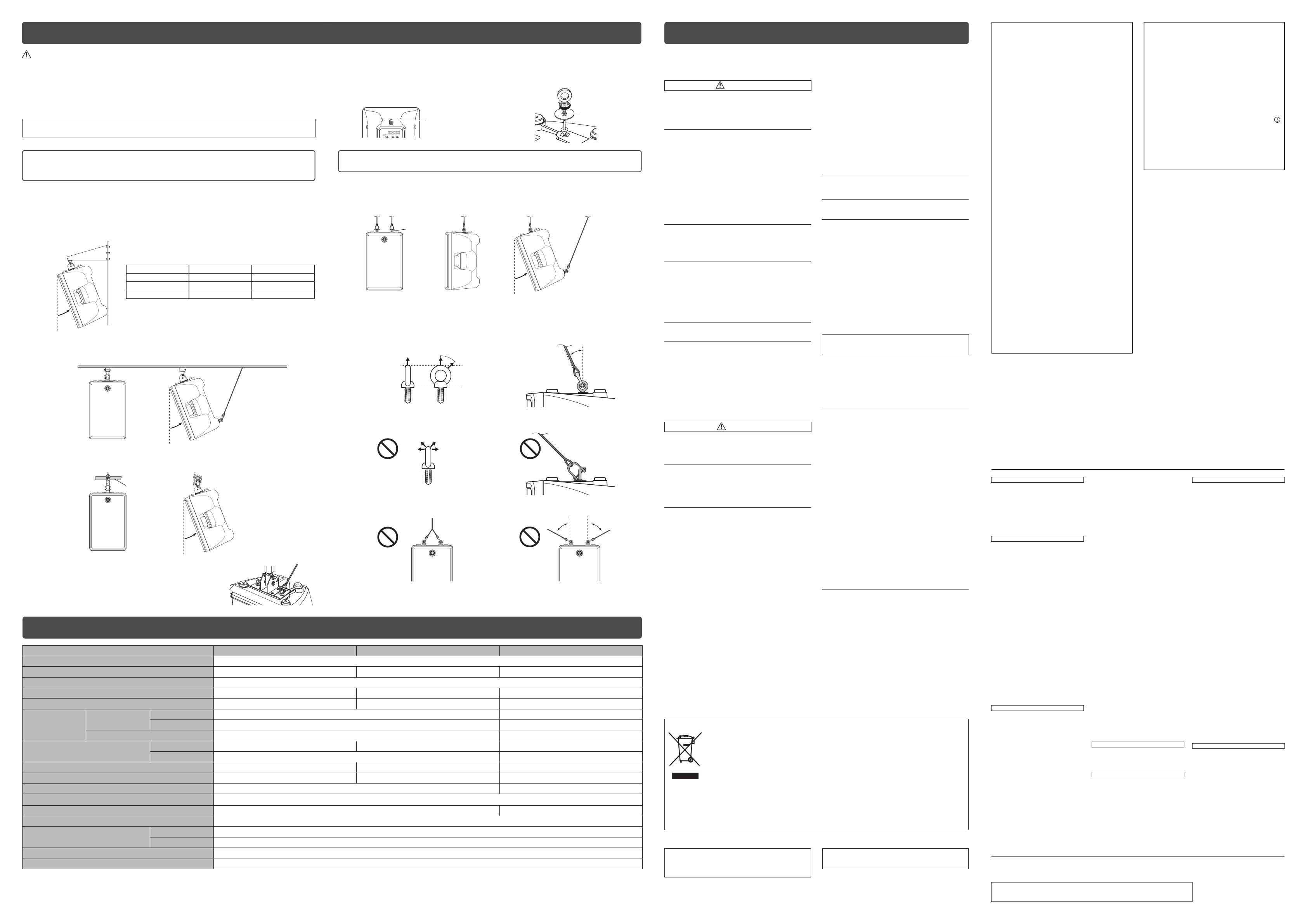
Installation Examples
Installation using separately sold Yamaha speaker
brackets
Attach the bracket to two screw holes at the bottom of the unit using commercially available screws
(M8x16mm) or eye bolts (M8x15mm). For details on installing the bracket, refer to the corresponding
manual.
Using the BWS251-300 or BWS251-400 wall mounting
bracket
Maximum tilt
angle
The tilt angle depends on the position relation between the speaker
and the wall. The maximum downward tilt angle is shown in the
following chart.
Maximum tilt angle BWS251-300 BWS251-400
DBR15 8° 17.5°
DBR12 11° 23°
DBR10 20° 35°
Using the BCS251 ceiling bracket
235923
Max. 45°
(Pullback point for DBR15
and DBR12 only)
Using the BBS251 baton bracket
235923
Max. 45°
Baton diameter
f
34 -
f
51
Note
In order to prevent the unit from falling down, attach the safety wire as
shown in the illustration.
CAUTION
• Before doing any installation or construction work, consult with your Yamaha dealer.
• For optimum safety, the installation should be checked thoroughly at regular intervals. Some fittings may deteriorate
over extended periods of time due to wear and/or corrosion.
• When choosing the installation location, suspension wire and mounting hardware, make sure all are strong enough to
support the weight of the speaker.
• Make sure to take measures to prevent the speaker from falling down in the event of a installation failure.
• When installing the safety wire to the wall, install it higher than the wire’s attachment point on the speaker, with as little
slack as possible. If the wire is too long, and the speaker happens to fall, the wire may snap as a result of too much
strain.
Yamaha cannot be held responsible for damage or injury caused by insufficient strength of the support
structure or improper installation.
Installation using eye bolts
Attach commercially-available eye bolts (M8 x 15 mm) to the screw holes located at the bottom (two locations)
and on the upper rear (one location, only for DBR15 and DBR12). Keep in mind that you will need two points
at the bottom to suspend the unit.
Note
Make sure to use eye bolts according to the standards and safety regulations in your area.
M8 eye bolt
Max. 45°
(Pullback point for
DBR15 and DBR12 only)
NOTICE
The strength of an eye bolt differs depending on the suspension angle. Make sure to use eye bolts within a
range of 0 to 45 degrees from a right angle (as shown).
Correct: Within 45° from a right angle
0°
45°
Max. 45°
Incorrect: Do not suspend the eye bolts as shown in the illustrations below.
Only one suspension point
More than 45° from a right angle
More than 45° More than 45°
PRECAUTIONS
General Specifications
General Specications DBR15 DBR12 DBR10
System Type 2-way, Bi-amp Powered Speaker, Bass-reflex Type
Frequency Range (-10dB) 49 Hz–20 kHz 52 Hz–20 kHz 55 Hz–20 kHz
Coverage Angle (Horizontal x Vertical) H90
°
x V60
°
Constant Directivity Horn
Measured Maximum SPL (Peak) IEC Noise@1m 132 dB SPL 131 dB SPL 129 dB SPL
Crossover 2.1 kHz 2.1 kHz 2.1 kHz
Power Amplier
Power Rating
Dynamic 1000 W (LF: 800 W, HF: 200 W) 700 W (LF: 500 W, HF: 200 W)
Continuous 465 W (LF: 400 W, HF: 65 W) 325 W (LF: 260 W, HF: 65 W)
Power Consumption 74 W 60 W
Components
LF 15" Cone, 2.5" Voice Coil 12" Cone, 2" Voice Coil 10" Cone, 2" Voice Coil
HF 1.4" Voice Coil, Compression Driver 1" Voice Coil, Compression Driver
Dimensions (WxHxD, Including Rubber Feet) 455 x 700 x 378 mm (17.9" x 27.6" x 14.9") 376 x 601 x 348 mm (14.8" x 23.7" x 13.7") 308 x 493 x 289 mm (12.1" x 19.4" x 11.4")
Net Weight 19.3 kg (42.6 lbs) 15.8 kg (34.8 lbs) 10.5 kg (23.2 lbs)
Handles Side x 2 Top x 1
Pole Socket
f
35 mm Bottom x 1
Rigging Points Bottom x 2, Rear x 1 (Fit for M8 x 15 mm) Bottom x 2 (Fit for M8 x 15 mm)
Optional Speaker Brackets BBS251, BCS251, BWS251-300, BWS251-400
I/O Connectors
Input INPUT1: Combo x1, INPUT2: Combo x 1 + RCA-pin x 2
Output XLR3-32 x 1 (CH1 Paralell Through or CH1+CH2 Mix)
Input Sensitivity (Level: Center) INPUT1: LINE: +10 dBu, MIC: -22 dBu, INPUT2: +10 dBu
Maximum Input Level INPUT1: LINE: +24 dBu, MIC: -8 dBu, INPUT2: +24 dBu
0 dBu is referenced to 0.775 Vrm
Specifications and descriptions in this owner’s manual are for information purposes only. Yamaha Corp. reserves the right to change or modify products or specifications at any time without prior notice. Since specifications,
equipment or options may not be the same in every locale, please check with your Yamaha dealer.
Pullback point (only for DBR15 and DBR12)
• When the unit is shipped from the factory, a seal is stuck
on the pullback point (screw hole). Make sure to peel off
the seal when using the pullback point.
• The DBR10 does not have a pullback point.
Pullback point
(M8 screw hole)
Upper rear of the unit
Securing the screws and eye
bolts
• Insert the screw or eye bolt through the
washer to attach them.
Apply thread-locking
uid to the eye bolt
PLEASE READ CAREFULLY BEFORE
PROCEEDING
Please keep this manual in a safe place for future
reference.
WARNING
Always follow the basic precautions listed below to
avoid the possibility of serious injury or even death from
electrical shock, short-circuiting, damages, re or other
hazards. These precautions include, but are not limited
to, the following:
Power supply/power cord
• Do not place the power cord near heat sources such
as heaters or radiators, and do not excessively bend or
otherwise damage the cord, place heavy objects on it,
or place it in a position where anyone could walk on, trip
over, or roll anything over it.
• Only use the voltage specified as correct for the device.
The required voltage is printed on the name plate of the
device.
• Use only the supplied power cord/plug.
• Check the electric plug periodically and remove any dirt
or dust which may have accumulated on it.
• Be sure to connect to an appropriate outlet with a
protective grounding connection. Improper grounding
can result in electrical shock, damage to the device(s), or
even fire.
Do not open
• This device contains no user-serviceable parts. Do not
open the device or attempt to disassemble the internal
parts or modify them in any way. If it should appear to be
malfunctioning, discontinue use immediately and have it
inspected by qualified Yamaha service personnel.
Water warning
• Do not expose the device to rain, use it near water or in
damp or wet conditions, or place on it any containers
(such as vases, bottles or glasses) containing liquids
which might spill into any openings. If any liquid such
as water seeps into the device, turn off the power
immediately and unplug the power cord from the AC
outlet. Then have the device inspected by qualified
Yamaha service personnel.
• Never insert or remove an electric plug with wet hands.
Fire warning
• Do not put burning items, such as candles, on the unit.
A burning item may fall over and cause a fire.
If you notice any abnormality
• When one of the following problems occur, immediately
turn off the power switch and disconnect the electric
plug from the outlet. Then have the device inspected by
Yamaha service personnel.
– The power cord or plug becomes frayed or damaged.
– It emits unusual smells or smoke.
– Some object has been dropped into the device.
– There is a sudden loss of sound during use of the
device.
• If this device should be dropped or damaged,
immediately turn off the power switch, disconnect
the electric plug from the outlet, and have the device
inspected by qualified Yamaha service personnel.
CAUTION
Always follow the basic precautions listed below to
avoid the possibility of physical injury to you or others,
or damage to the device or other property. These
precautions include, but are not limited to, the following:
Power supply/power cord
• When removing the electric plug from the device or an
outlet, always hold the plug itself and not the cord. Pulling
by the cord can damage it.
• Remove the electric plug from the outlet when the device
is not to be used for extended periods of time, or during
electrical storms.
Location
• Do not place the device in an unstable position where it
might accidentally fall over.
• Do not block the vents. This device has ventilation holes at
the rear to prevent the internal temperature from becoming
too high. In particular, do not place the device on its
side or upside down. Inadequate ventilation can result in
overheating, possibly causing damage to the device(s),
or even fire.
• When installing the device:
– Do not cover it with any cloth.
– Do not install it on a carpet or rug.
– Do not use the device in a confined, poorly-ventilated
location.
Inadequate ventilation can result in overheating, possibly
causing damage to the device(s), or even fire. Make sure
that there is adequate space around the device: at least
30cm above, 30cm at the sides and 30cm behind.
• Do not use the speaker’s handles for suspended
installation. Doing so can result in damage or injury.
• Do not hold the bottom of the device when transporting or
moving it. In doing so, you may pinch your hands under
the device, and result in injury.
• Do not press the rear panel of the device against the wall.
Doing so may cause the plug to come in contact with the
wall and detach from the power cord, resulting in short
circuiting, malfunction, or even fire.
• Do not place the device in a location where it may come
into contact with corrosive gases or salt air. Doing so may
result in malfunction.
• Before moving the device, remove all connected cables.
• When setting up the device, make sure that the AC outlet
you are using is easily accessible. If some trouble or
malfunction occurs, immediately turn off the power switch
and disconnect the plug from the outlet. Even when the
power switch is turned off, electricity is still flowing to the
product at the minimum level. When you are not using the
product for a long time, make sure to unplug the power
cord from the wall AC outlet.
• Always consult qualified Yamaha service personnel if the
device installation requires construction work, and make
sure to observe the following precautions.
– Choose mounting hardware and an installation location
that can support the weight of the device.
– Avoid locations that are exposed to constant vibration.
– Use the required tools to install the device.
– Inspect the device periodically.
Connections
• Before connecting the device to other devices, turn off the
power for all devices. Before turning the power on or off
for all devices, set all volume levels to minimum.
Maintenance
• Remove the power plug from the AC outlet when cleaning
the device.
Handling caution
• Do not insert your fingers or hands in any gaps or
openings on the device (vents, etc.).
• Avoid inserting or dropping foreign objects (paper,
plastic, metal, etc.) into any gaps or openings on the
device (vents, etc.) If this happens, turn off the power
immediately and unplug the power cord from the AC
outlet. Then have the device inspected by qualified
Yamaha service personnel.
• Do not rest your weight on the device or place heavy
objects on it, and avoid use excessive force on the
buttons, switches or connectors.
• Do not use the device for a long period of time at a high
or uncomfortable volume level, since this can cause
permanent hearing loss. If you experience any hearing
loss or ringing in the ears, consult a physician.
• Do not operate the device if the sound is distorting.
Prolonged use in this condition could cause overheating
and result in fire.
• Do not pull the cables connected to the microphones, etc.
Yamaha cannot be held responsible for damage caused
by improper use or modifications to the device, or data
that is lost or destroyed.
(PA-3)
NOTICE
To avoid the possibility of malfunction/ damage to the
product, damage to data, or damage to other property,
follow the notices below.
Handling and maintenance
• Do not expose the device to excessive dust or vibration,
or extreme cold or heat (such as in direct sunlight, near a
heater, or in a car during the day), in order to prevent the
possibility of panel disfiguration, unstable operation, or
damage to the internal components.
• Do not place vinyl, plastic or rubber objects on the device,
since this might discolor the panel.
• When cleaning the device, use a dry and soft cloth. Do not
use paint thinners, solvents, cleaning fluids, or chemical-
impregnated wiping cloths.
• Condensation can occur in the device due to rapid,
drastic changes in ambient temperature—when the device
is moved from one location to another, or air conditioning
is turned on or off, for example. Using the device while
condensation is present can cause damage. If there is
reason to believe that condensation might have occurred,
leave the device for several hours without turning on the
power until the condensation has completely dried out.
• When turning on the AC power in your audio system,
always turn on the device LAST, to avoid speaker
damage. When turning the power off, the device should
be turned off FIRST for the same reason.
• Interference From Cell Phones
Using a cell phone near the speaker system can induce
noise. If this occurs, move the cell phone further away
from the speaker system.
• Air blowing out of the bass reflex ports is normal, and
often occurs when the speaker is handling program
material with heavy bass content.
• Always turn the power off when the device is not in use.
Connectors
• XLR-type connectors are wired as follows (IEC60268
standard): pin 1: ground, pin 2: hot (+), and pin 3: cold (-).
Information for Users on Collection and Disposal of Old Equipment
This symbol on the products, packaging, and/or accompanying documents means that used electrical
and electronic products should not be mixed with general household waste.
For proper treatment, recovery and recycling of old products, please take them to applicable collection
points, in accordance with your national legislation and the Directives 2002/96/EC.
By disposing of these products correctly, you will help to save valuable resources and prevent any
potential negative effects on human health and the environment which could otherwise arise from
inappropriate waste handling.
For more information about collection and recycling of old products, please contact your local
municipality, your waste disposal service or the point of sale where you purchased the items.
[For business users in the European Union]
If you wish to discard electrical and electronic equipment, please contact your dealer or supplier for
further information.
[Information on Disposal in other Countries outside the European Union]
This symbol is only valid in the European Union. If you wish to discard these items, please contact your
local authorities or dealer and ask for the correct method of disposal.
(weee_eu_en_01)
FCC INFORMATION (U.S.A.)
1. IMPORTANT NOTICE: DO NOT MODIFY THIS
UNIT!
This product, when installed as indicated in the
instructions contained in this manual, meets FCC
requirements. Modifications not expressly approved
by Yamaha may void your authority, granted by the
FCC, to use the product.
2. IMPORTANT: When connecting this product to
accessories and/or another product use only high
quality shielded cables. Cable/s supplied with
this product MUST be used. Follow all installation
instructions. Failure to follow instructions could void
your FCC authorization to use this product in the
USA.
3. NOTE: This product has been tested and found
to comply with the requirements listed in FCC
Regulations, Part 15 for Class “B” digital devices.
Compliance with these requirements provides a
reasonable level of assurance that your use of
this product in a residential environment will not
result in harmful interference with other electronic
devices. This equipment generates/uses radio
frequencies and, if not installed and used according
to the instructions found in the users manual, may
cause interference harmful to the operation of
other electronic devices. Compliance with FCC
regulations does not guarantee that interference
will not occur in all installations. If this product is
found to be the source of interference, which can
be determined by turning the unit “OFF” and “ON”,
please try to eliminate the problem by using one of
the following measures:
Relocate either this product or the device that is
being affected by the interference.
Utilize power outlets that are on different branch
(circuit breaker or fuse) circuits or install AC line
filter/s.
In the case of radio or TV interference, relocate/
reorient the antenna. If the antenna lead-in is 300
ohm ribbon lead, change the lead-in to co-axial type
cable.
If these corrective measures do not produce
satisfactory results, please contact the local retailer
authorized to distribute this type of product. If
you can not locate the appropriate retailer, please
contact Yamaha Corporation of America, Electronic
Service Division, 6600 Orangethorpe Ave, Buena
Park, CA90620
The above statements apply ONLY to those
products distributed by Yamaha Corporation of
America or its subsidiaries.
* This applies only to products distributed by YAMAHA
CORPORATION OF AMERICA.
(class B)
IMPORTANT NOTICE FOR THE UNITED KINGDOM
Connecting the Plug and Cord
WARNING: THIS APPARATUS MUST BE EARTHED
IMPORTANT. The wires in this mains lead are coloured
in accordance with the following code:
GREEN-AND-YELLOW : EARTH
BLUE : NEUTRAL
BROWN : LIVE
As the colours of the wires in the mains lead of this
apparatus may not correspond with the coloured
markings identifying the terminals in your plug
proceed as follows:
The wire which is coloured GREEN-and-YELLOW
must be connected to the terminal in the plug which is
marked by the letter E or by the safety earth symbol
or colored GREEN or GREEN-and-YELLOW.
The wire which is coloured BLUE must be connected
to the terminal which is marked with the letter N or
coloured BLACK.
The wire which is coloured BROWN must be
connected to the terminal which is marked with the
letter L or coloured RED.
(3 wires)
In Finland: Laite on liitettävä suojamaadoituskoskettimilla
varustettuun pistorasiaan.
In Norway: Apparatet må tilkoples jordet stikkontakt.
In Sweden: Apparaten skall anslutas till jordat uttag.
(class I hokuo)
이 기기는 가정용(B급) 전자파적합기기로서 주로 가정에서
사용하는 것을 목적으로 하며, 모든 지역에서 사용할 수
있습니다.
(class b korea)
HEAD OFFICE
Yamaha Corporation, Audio Products Sales and Marketing Division
Nakazawa-cho 10-1, Naka-ku, Hamamatsu, Japan 430-8650
CANADA
Yamaha Canada Music Ltd.
135 Milner Avenue, Toronto, Ontario,
M1S 3R1, Canada
Tel: 416-298-1311
U.S.A.
Yamaha Corporation of America
6600 Orangethorpe Avenue, Buena Park, CA 90620,
U.S.A.
Tel: 714-522-9011
MEXICO
Yamaha de México, S.A. de C.V.
Av. Insurgentes Sur 1647 Piso 9, Col. San José
Insurgentes, Delegación Benito Juárez, México,
D.F., C.P. 03900
Tel: 55-5804-0600
BRAZIL
Yamaha Musical do Brasil Ltda.
Rua Joaquim Floriano, 913 - 4º andar, Itaim Bibi,
C
EP 04534-013 São Paulo, SP. BRAZIL
Tel: 011-3704-1377
ARGENTINA
Yamaha Music Latin America, S.A.,
Sucursal Argentina
Olga Cossettini 1553, Piso 4 Norte,
Madero Este-C1107CEK
Buenos Aires, Argentina
Tel: 011-4119-7000
VENEZUELA
Yamaha Music Latin America, S.A.,
Sucursal Venezuela
C.C. Manzanares Plaza P4
Ofic. 0401- Manzanares-Baruta
Caracas Venezuela
Tel: 58-212-943-1877
PANAMA AND OTHER LATIN
AMERICAN COUNTRIES/
CARIBBEAN COUNTRIES
Yamaha Music Latin America, S.A.
Torre Banco General, Piso No.7, Marbella,
Calle 47 y Aquilino de la Guardia,
Ciudad de Panamá, República de Panamá
Tel: +507-269-5311
THE UNITED KINGDOM/IRELAND
Yamaha Music Europe GmbH (UK)
Sherbourne Drive, Tilbrook, Milton Keynes,
MK7 8BL, U.K.
Tel: 01908-366700
GERMANY
Yamaha Music Europe GmbH
Siemensstraße 22-34, 25462 Rellingen, Germany
Tel: 04101-3030
SWITZERLAND/LIECHTENSTEIN
Yamaha Music Europe GmbH
Branch Switzerland in Zürich
Seefeldstrasse 94, 8008 Zürich, Switzerland
T
el: 044-387-8080
AUSTRIA/BULGARIA
Yamaha Music Europe GmbH Branch Austria
Schleiergasse 20, A-1100 Wien, Austria
Tel: 01-60203900
CZECH REPUBLIC/HUNGARY/
ROMANIA/SLOVAKIA/SLOVENIA
Yamaha Music Europe GmbH
Branch Austria (Central Eastern Europe Office)
Schleiergasse 20, A-1100 Wien, Austria
Tel: 01-60203900
POLAND/LITHUANIA/LATVIA/ESTONIA
Yamaha Music Europe GmbH
Branch Poland Office
ul. Wrotkowa 14 02-553 Warsaw, Poland
Tel: 022-500-2925
MALTA
Olimpus Music Ltd.
The Emporium, Level 3, St. Louis Street Msida
MSD06
Tel: 02133-2144
NETHERLANDS/BELGIUM/
LUXEMBOURG
Yamaha Music Europe Branch Benelux
Clarissenhof 5-b, 4133 AB Vianen, Netherlands
Tel: 0347-358 040
FRANCE
Yamaha Music Europe
7 rue Ambroise Croizat, Zone d'activites Pariest,
77183 Croissy-Beaubourg, France
Tel: 01-64-61-4000
ITALY
Yamaha Music Europe GmbH, Branch Italy
Viale Italia 88, 20020 Lainate (Milano), Italy
Tel: 02-935-771
SPAIN/PORTUGAL
Yamaha Music Europe GmbH Ibérica, Sucursal
en España
Ctra. de la Coruna km. 17,200, 28231
Las Rozas (Madrid), Spain
Tel: +34-91-639-88-88
GREECE
Philippos Nakas S.A. The Music House
147 Skiathou Street, 112-55 Athens, Greece
Tel: 01-228 2160
SWEDEN/FINLAND/ICELAND
Yamaha Music Europe GmbH Germany filial
Scandinavia
J. A. Wettergrensgata 1, Box 30053
S-400 43 Göteborg, Sweden
Tel: +46 31 89 34 00
DENMARK
Yamaha Music Europe GmbH, Tyskland – filial
Denmark
G
eneratorvej 6A, DK-2730 Herlev, Denmark
Tel: 44 92 49 00
NORWAY
Yamaha Music Europe GmbH Germany -
Norwegian Branch
Grini Næringspark 1, N-1361 Østerås, Norway
Tel: 67 16 78 00
RUSSIA
Yamaha Music (Russia) LLC.
Room 37, bld. 7, Kievskaya street, Moscow,
121059, Russia
Tel: 495 626 5005
OTHER EUROPEAN COUNTRIES
Yamaha Music Europe GmbH
Siemensstraße 22-34, 25462 Rellingen, Germany
Tel: +49-4101-3030
Yamaha Music Gulf FZE
Office JAFZA 16-512, P.O.Box 17328,
Jebel Ali - Dubai, UAE
T
el: +971-4-881-5868
TURKEY
Yamaha Music Europe GmbH
Merkezi Almanya Türkiye İstanbul Şubesi
Maslak Meydan Sokak No:5 Spring Giz Plaza
Bağ?ms?z Böl. No:3, 34398 Şişli İstanbul
Tel: +90-212-999-8010
CYPRUS
Yamaha Music Europe GmbH
Siemensstraße 22-34, 25462 Rellingen, Germany
Tel: 04101-3030
OTHER COUNTRIES
Yamaha Music Gulf FZE
Office JAFZA 16-512, P.O.Box 17328,
Jebel Ali - Dubai, U.A.E
Tel: +971-4-881-5868
THE PEOPLE’S REPUBLIC OF CHINA
Yamaha Music & Electronics (China) Co.,Ltd.
2F, Yunhedasha, 1818 Xinzha-lu, Jingan-qu,
Shanghai, China
Tel: 021-6247-2211
INDIA
Yamaha Music India Pvt. Ltd.
Spazedge building, Ground Floor, Tower A, Sector
47, Gurgaon- Sohna Road, Gurgaon, Haryana, India
Tel: 0124-485-3300
INDONESIA
PT. Yamaha Musik Indonesia (Distributor)
Yamaha Music Center Bldg. Jalan Jend. Gatot
Subroto Kav. 4, Jakarta 12930, Indonesia
Tel: 021-520-2577
KOREA
Yamaha Music Korea Ltd.
8F, 9F, Dongsung Bldg. 158-9 Samsung
-Dong,
Kangnam-Gu, Seoul, Korea
Tel: 02-3467-3300
MALAYSIA
Yamaha Music (Malaysia) Sdn., Bhd.
No.8, Jalan Perbandaran, Kelana Jaya, 47301
Petaling Jaya, Selangor, Malaysia
Tel: 03-78030900
SINGAPORE
Yamaha Music (Asia) Private Limited
Block 202 Hougang Street 21, #02-00,
Singapore 530202, Singapore
Tel: 65-6747-4374
TAIWAN
Yamaha Music & Electronics Taiwan Co.,Ltd.
3F, No.6, Section 2 Nan-Jing East Road, Taipei,
Taiwan R.O.C.
Tel: 02-2511-8688
THAILAND
Siam Music Yamaha Co., Ltd.
3, 4, 15 and 16th floor, Siam Motors Building,
891/1 Rama 1 Road, Wangmai,
Pathumwan, Bangkok 10330, Thailand
Tel: 02-215-2622
VIETNAM
Yamaha Music Vietna m Company Limited
15th Floor, Nam A Bank Tower, 201-203 Cach
Mang Thang Tam St., Ward 4, Dist.3,
Ho Chi Minh City, Vietnam
Tel: +84-8-3818-1122
OTHER ASIAN COUNTRIES
Yamaha Corporation
Sales & Marketing Division
Nakazawa-cho 10-1, Naka-ku, Hamamatsu,
Japan 430-8650
Tel: +81-53-460-2312
AUSTRALIA
Yamaha Music Australia Pty. Ltd.
Level 1, 99 Queensbridge Street, Southbank,
Victoria 3006, Australia
Tel: 3-9693-5111
COUNTRIES AND TRUST
TERRITORIES IN PACIFIC OCEAN
Yamaha Corporation
Sales & Marketing Division
Nakazawa-cho 10-1, Naka-ku, Hamamatsu,
Japan 430-8650
Tel: +81-53-460-2312
NORTH AMERICA
CENTRAL & SOUTH AMERICA
EUROPE
AFRICA
MIDDLE EAST
ASIA
OCEANIA
PA36
For details of products, please contact your nearest Yamaha representative or the authorized distributor listed below.
Yamaha Pro Audio global web site
http://www.yamahaproaudio.com/
Yamaha Manual Library
http://www.yamaha.co.jp/manual/
C.S.G., PA Development Division
© 2014 Yamaha Corporation
Published 07/2014 KSZC*.*-01A0
Printed in Indonesia

